Pptc heating element having varying power density

Active Publication Date: 2022-04-21
LITTELFUSE INC
View PDF9 Cites 0 Cited by
  • Summary
  • Abstract
  • Description
  • Claims
  • Application Information

AI Technical Summary

Benefits of technology

[0009]To mitigate the challenges described above, a new method for controlling power density in pPTC heating devices is disclosed herein. The invention describes a device having different power densities over the surface area of the device. The method comprises using a single pPTC base material having a constant resistivity. Power density over the surface area of the device is controlled by splitting the upper and lower conductive layers into sectioned portions to control the current path through the device, and thus the overall resistivity of the device. By varying the size and number of the sectioned portions of the conductive layers over the surface area of the device, different areas of resistivity, and therefore different power densities, can be achieved in a single device.
[0010]The sectioned portions operate as resistors connected in series. Each sectioned portion will be smaller in size and, as there will be multiple sectioned portions connected in series, each sectioned portion would be exposed to a lower voltage. By changing the, sectioned portions and the way the sectioned portion

Problems solved by technology

Varying supply voltage in most cases requires additional components, thus increasing the cost of production.
Changing the formulation of the pPTC material to achieve d

Method used


Image

  • Pptc heating element having varying power density
  • Pptc heating element having varying power density
  • Pptc heating element having varying power density

Examples


Example

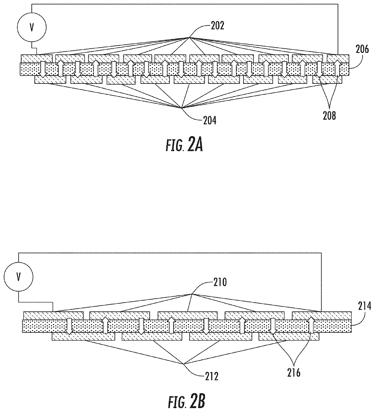
[0020]FIG. 2 shows a schematic side views of two exemplary proof-of-concept embodiments of devices in accordance with the present invention. As shown in FIG. 2(A), the upper electrically conductive layer 202 and the lower electrically conductive layer 204 have been sectioned into several portions. In this embodiment, the portions are positioned such as to force the current to oscillate between the upper layer 202 and the lower layer 204 as the current traverses the device. The path of the current as it traverses the device from left to right is shown by the arrows, showing that the current oscillates between upper layer 202 and lower layer 204 through pPTC layer 206. The passage of the current though resistive layer 206 multiple times as the current traverses the device acts as a series of resistors, with a commensurate voltage drop with each transition through the pPTC layer 206.

[0021]In preferred embodiments of the invention, the sectioned portions of upper layer 202 and lower lay...


PUM


Abstract

A pPTC heating device having areas with different power densities distributed over the surface of the device. The device is constructed using a base layer composed of a pPTC material having a layer of sectioned conductive plates disposed over and under the layer of pPTC such as to control the path of the current through the device, thereby controlling resistance of the device and the power density of the device.

Description

BACKGROUND OF THE INVENTION[0001]A positive temperature coefficient (PTC) material is a material that exhibits a positive temperature coefficient, meaning that as its temperature increases its resistance increases proportionately. Typically, current can be passed through devices composed of a PTC material until the temperature of the material reaches a specific design temperature, at which point the resistance rapidly rises, effectively cutting off the flow of current.[0002]A polymeric PTC (pPTC) is a PTC device composed of a non-conductive crystalline polymer infused with carbon particles. When below the design temperature, the polymer is in a crystalline state with the carbon particles forming conductive paths through the polymer. If too much current is passed, the device will heat and the polymer will change to an amorphous state, thereby separating the carbon particles and breaking the current paths. Once the device is cooled, the polymer will return to a crystalline state, ther...

Claims


Application Information

Patent Timeline
IPC IPC(8): H05B3/14H02H9/02
CPCH05B3/146H05B2203/02H02H9/026H05B3/02H05B3/03H01C7/021H01C7/02H01C7/027H01C13/02
Inventor FESSHAIE, EFREMKABISIUS, PAULIUS
Owner LITTELFUSE INC
Why Eureka
Try Eureka