Buried pipeline cathodic protection device and method

A cathodic protection and buried pipeline technology, applied in the field of electric power, can solve the problems of cathodic protection potential fluctuations, difficulty in troubleshooting, increasing construction volume and cycle, etc., to maintain stable physical properties, reduce engineering costs, and extend service life. Effect

Active Publication Date: 2020-01-03
NORTHEAST DIANLI UNIVERSITY
View PDF7 Cites 0 Cited by
  • Summary
  • Abstract
  • Description
  • Claims
  • Application Information

AI Technical Summary

Problems solved by technology

Due to the long construction period of the pipeline, the cathodic protection project cannot be carried out at the same time as the main project, and the cathodic protection project can only start after the buried pipeline project is completed, which increases the construction volume and cycle; for the old pipeline with frequent leaks, the cathodic protection project is added more difficult
[0006] The traditional cathodic protection process is cumbersome, requiring the establishment of a cathodic protection station, which limits the application of cathodic protection engineering; the soil between the auxiliary anode and the pipeline is used as the electrolyte, which is greatly affected by the environment, and the soil resistance is unstable, resulting in large fluctuations in the cathodic protection potential. Current density is difficult to control; faults are difficult to troubleshoot. After the test pile and anode grounding bed are damaged, they cannot be seen from the ground surface, and the specific location of the damaged pipe section cannot be judged; Component power supply, after the cable is damaged, it is impossible to accurately determine the location of the damage, and it is also impossible to accurately find out whether the fault is on the test pile or the cable, which increases the difficulty of troubleshooting and brings difficulties to equipment maintenance.

Method used


Image

  • Buried pipeline cathodic protection device and method
  • Buried pipeline cathodic protection device and method
  • Buried pipeline cathodic protection device and method

Examples


Embodiment 1

[0080] Embodiment 1: a kind of buried pipeline cathodic protection method and device of embodiment 1, comprises the following steps:

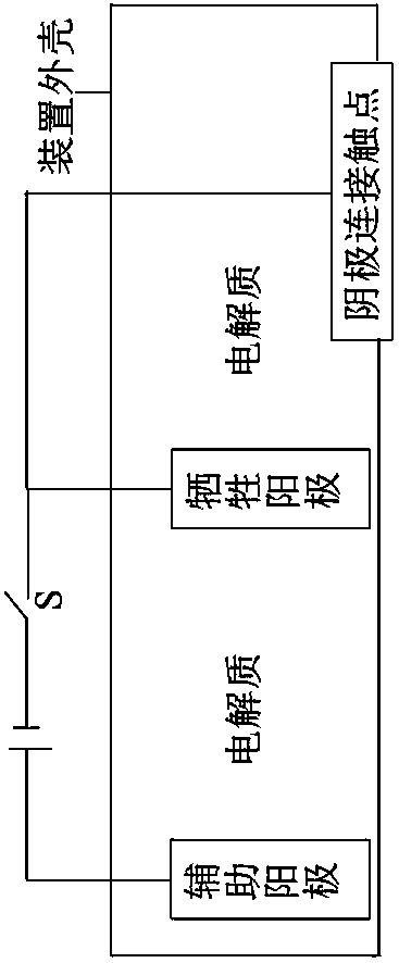
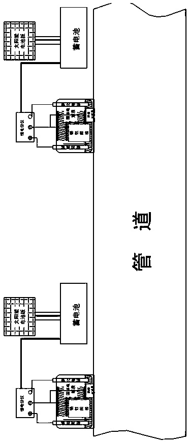
[0081] (1) Impressed current protection system

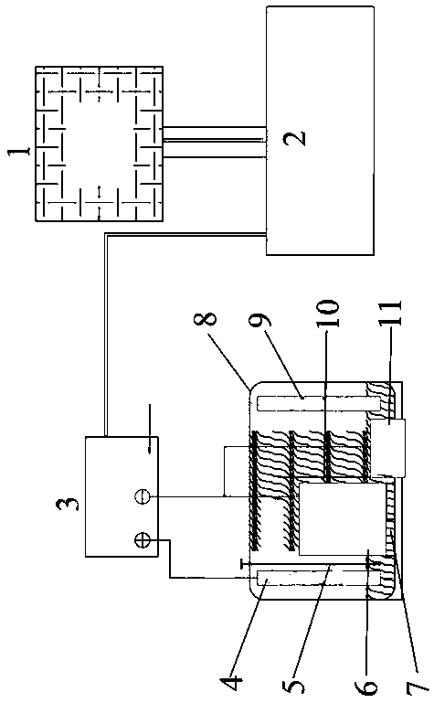
[0082] a. The power supply of the buried pipeline cathodic combined protection device: the model is WDY-3000s and the power is 3000w. The solar panel is electrically connected to the battery. The battery type is D-lead battery with a capacity of 30AH. It works for 6 hours under sufficient light conditions, and the storage capacity of the battery is 18kw. The solar panel absorbs the power of the sun and transmits it to the battery for storage, which constitutes the power supply of the buried pipeline cathodic joint protection device. The battery terminal is connected to the potentiostat, and the solar panel converts solar energy into electrical energy in the field, stores it in the battery, and provides direct current for the potentiostat, which completely overcomes the technical difficulty of the...

Embodiment 2

[0108] Embodiment 2: In the steps of a kind of buried pipeline cathodic protection method and device of embodiment 2 (1) (2) (4) (5) steps are the same as embodiment 1, wherein step (3) is different, specific steps yes:

[0109] (3) Preparation of quasi-solid electrolyte

[0110] 30% zinc sulfate solution is added dropwise to 40% sodium hydroxide solution, and mixed in an environment with a water bath temperature of 40° C. to form a flocculent quasi-solid electrolyte. The pH value of the formed quasi-solid electrolyte is 9.2, the resistivity of the prepared electrolyte is 361Ω·cm, and the volatilization rate of the prepared electrolyte is 0.035g·(kg·d) -1 . The electrolyte was subjected to an electrolysis experiment, and it was found that there was metal zinc in the electrolyte after electrolysis. Metal zinc is electrolyzed from the electrolyte, attached to the quasi-solid electrolyte, and exists as tiny particles. In this case, the specific surface area of ​​metal zinc is...

Embodiment 3

[0113] Embodiment 3: (1) (2) (3) (4) (5) a, b steps are the same as embodiment 2 in the step of a kind of buried pipeline cathodic protection method and device of embodiment 3, wherein step (5) )c is different, the specific steps are:

[0114] (5) Construction and operation of buried pipeline cathodic combined protection device

[0115] c. Operation of cathodic combined protection device for buried pipeline

[0116] In order to explore the protective effect of cathodic protection devices on buried pipelines, this experiment simulates buried water pipelines with Q235 carbon steel pipes. Take two sections of Q235 carbon steel pipes, the pipe diameter is 25mm, the pipe length is 500mm, and they are respectively labeled #1 and #2. Take the #2 pipe section as a blank control test, and carry out cathodic protection on the #1 pipe section; in this experiment, the two sections of pipes are connected in series , buried in the soil, the buried depth is 800mm, the soil resistivity is 2...


PUM

PropertyMeasurementUnit
electrical resistivityaaaaaaaaaa
thicknessaaaaaaaaaa
electrical resistivityaaaaaaaaaa

Abstract

The invention discloses a novel cathode protection device of buried pipeline, and belongs to the technical field of electric power. The method aims at analyzing defects existing in the aspect of long-distance pipeline of traditional cathode protection, innovation is carried out on the basis of sacrificial anode and current cathode protection technology, and the novel cathode protection device andmethod of the buried pipeline for the sacrificial anode and current cathode protection are researched and developed. The device comprises a power supply, a potentiostat, an auxiliary anode, a reference electrode, a cathode protection connection contact point and a quasi-solid electrolyte of the novel cathode combined protection device of the buried pipeline. The device is simple and convenient, solar power generation system is used as the cathode protection power supply, a cathode protection station and a laying cable do not need to be built, can be put into a field power-free cathode protection project at any time, so that engineering cost is reduced.

Description

technical field [0001] The invention belongs to the technical field of electric power. Background technique [0002] The buried pipelines of thermal power plants in China are mostly made of carbon steel, the pipelines have a long transmission distance, the soil environment is complex and changeable, the inner wall has no anti-corrosion measures, and the outer wall is painted with petroleum asphalt anti-corrosion coating. Due to the continuous corrosion of the inner wall by the water quality in the pipe and the continuous corrosion of the outer wall by the external soil, the quality of the anti-corrosion layer of some pipelines cannot meet the design standards, the construction is not standardized, and the anti-corrosion measures are not in place. During the long-term operation, the corrosion factors and buried The long-term effect of the pipeline has caused serious corrosion of the buried pipeline. [0003] The commonly used anti-corrosion measures for buried pipelines incl...

Claims


Application Information

Patent Timeline
Patent Type & Authority Patents(China)
IPC IPC(8): C23F13/06C23F13/04
CPCC23F13/04C23F13/06
Inventor 施云芬张世龙孙树森魏嘉馨
Owner NORTHEAST DIANLI UNIVERSITY
Why Eureka
Try Eureka