Rocket propulsion system, method, and spacecraft

a rocket propulsion system and rocket technology, applied in the direction of gas/liquid distribution and storage, fuel cells, cosmonautic components, etc., can solve the problems of unnecessary heat exchangers, achieve low acceleration, increase the payload of spacecraft, and increase the efficiency of the rocket propulsion system

Pending Publication Date: 2022-04-28
ARIANEGRP GMBH
View PDF4 Cites 0 Cited by
  • Summary
  • Abstract
  • Description
  • Claims
  • Application Information

AI Technical Summary

Benefits of technology

[0019]In accordance with a further configuration of the method, thrust is generated primarily by means of the main propulsion unit in the propulsion phase, and in the ballistic phase by means of the at least one auxiliary propulsion unit supplied by the at least two gas pressure accumulators. In this way, at least a low level of acceleration can be maintained, even in the ballistic phase, of a spacecraft equipped with the rocket propulsion system, so that the propellants settle preferably in the region of the lower surfaces of the tank and any re-ignition of the main propulsion unit is possible, without any problems, by sucking in the propellants with the aid of the (turbo) pumps of the main lines.
[0020]Furthermore, the above-cited object is achieved by a spacecraft equipped with at least one rocket propulsion system. As a consequence, the payload of the spacecraft is increased, inter alia, by virtue of the significant increase in efficiency of the rocket propulsion system. The spacecraft can be, for example, an upper stage, or a final stage, of a multi-stage rocket, a space transporter, a satellite, a manned spaceship, or an unmanned space probe for earth orbit or an interplanetary orbit.

Problems solved by technology

Furthermore, heat exchangers are unnecessary in this context.

Method used


Image

  • Rocket propulsion system, method, and spacecraft

Examples


Embodiment Construction

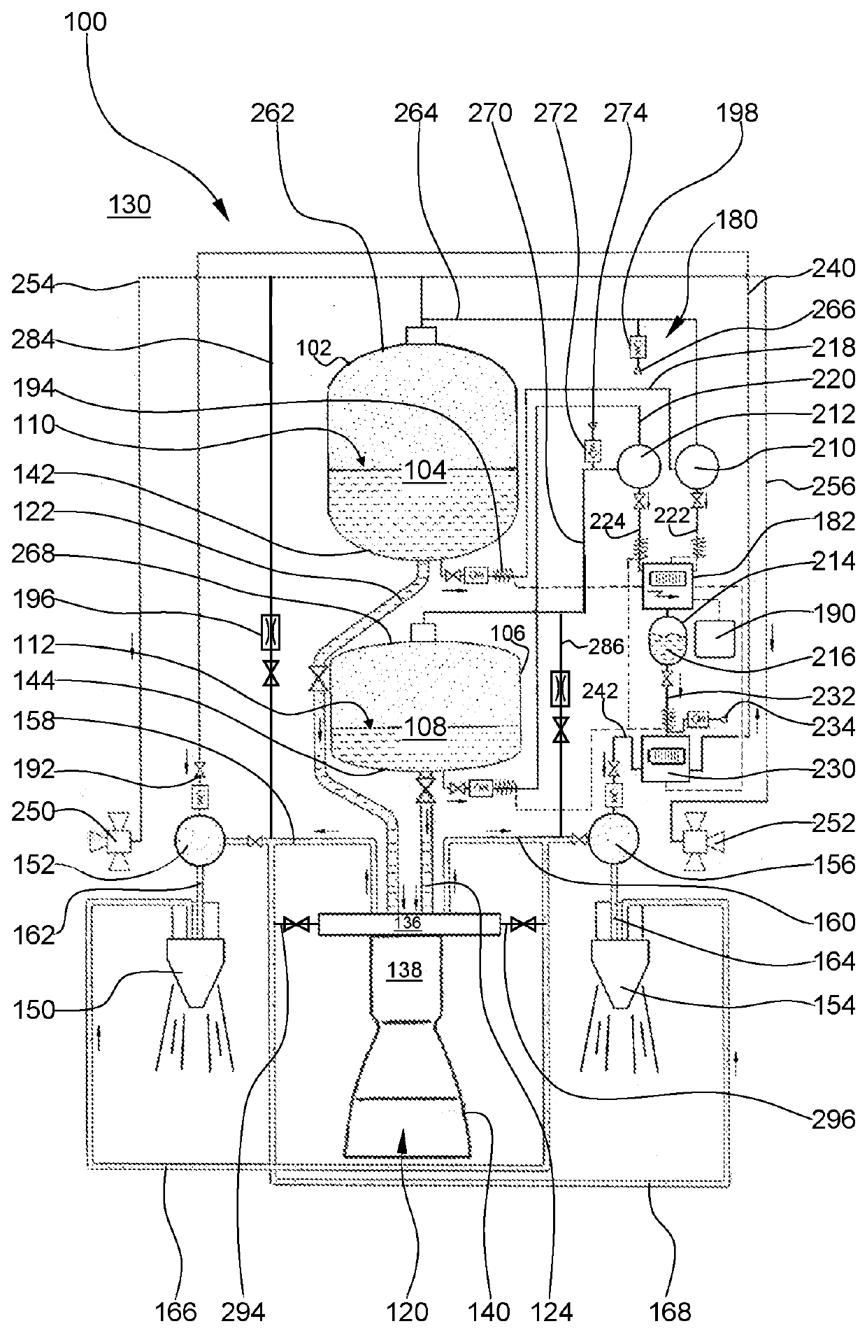
[0023]The FIGURE illustrates a highly simplified diagram of a rocket propulsion system in accordance with the invention. A rocket propulsion system 100, or a complete rocket propulsion unit, comprises, inter alia, a first cryogenic tank 102 for the storage of a first propellant 104, and a second cryogenic tank 106 for the storage of a second propellant 108, wherein a main propulsion unit 120, which can be ignited multiple times, can be supplied with the propellants 104, 108 in a liquid phase by way of a first and a second main line 122, 124. Feeding of the main propulsion unit 120 with the propellants 104, 108 by way of the main lines 122, 124 takes place, for example, in a propulsion phase, or a so-called boost phase, or a launch phase, of a spacecraft 130 (not shown) equipped with the rocket propulsion system 100. If necessary, the propulsion phase of the spacecraft 130 can also be initiated in space by the ignition of the main propulsion unit 120. The spacecraft 130 can take the ...


PUM

PropertyMeasurementUnit
pressureaaaaaaaaaa
pressureaaaaaaaaaa
accelerationaaaaaaaaaa

Abstract

A rocket propulsion system comprising a first cryogenic tank and a second cryogenic tank, wherein the first cryogenic tank is filled with a first propellant, and the second cryogenic tank is filled with a second propellant, for purposes of feeding at least one repeatedly ignitable main propulsion unit in a propulsion phase of the rocket propulsion system. For purposes of tank pressurization via at least a low level of acceleration in a ballistic phase, a first auxiliary propulsion unit can be operated by means of a first gas pressure accumulator, and at least one further auxiliary propulsion unit can be operated by means of a further gas pressure accumulator, and the rocket propulsion system is assigned an energy conversion unit, which is designed at least to charge the first and the second gas pressure accumulator, preferably in the ballistic phase.

Description

CROSS-REFERENCES TO RELATED APPLICATIONS[0001]This application claims the benefit of the German patent application No. 102020128007.6 filed on Oct. 23, 2020, the entire disclosures of which are incorporated herein by way of reference.FIELD OF THE INVENTION[0002]The invention relates firstly to a rocket propulsion system comprising a first cryogenic tank and a second cryogenic tank, wherein the first cryogenic tank is filled with a first propellant, and the second cryogenic tank is filled with a second propellant, for purposes of feeding at least one repeatedly ignitable main propulsion unit in a propulsion phase of the rocket propulsion system.BACKGROUND OF THE INVENTION[0003]US 2014 / 0203148 A1 discloses a cryogenic propulsion unit arrangement. The above-cited cryogenic propulsion unit comprises, inter alia, a re-ignitable main propulsion unit and a first cryogenic tank, which is connected to the main propulsion unit so as to supply it with a first propellant. Also provided are a fi...

Claims


Application Information

Patent Timeline
Patent Type & Authority Applications(United States)
IPC IPC(8): B64G1/40B64G1/42F02K9/42F17C7/02H01M8/0656
CPCB64G1/401B64G1/402B64G1/423F02K9/425F17C7/02H01M8/0656H01M2250/20F17C2265/066F17C2205/0332F17C2221/012F17C2221/011F17C2270/0197F17C2223/0161F02K9/50F02K9/88F02K9/42Y02E60/32Y02E60/50
Inventor HESSEL, CHRISTIAN
Owner ARIANEGRP GMBH
Why Eureka
Try Eureka