Waveguide-type optical multiplexer/demultiplexer

Inactive Publication Date: 2005-09-20
HITACHI CABLE
View PDF10 Cites 15 Cited by
  • Summary
  • Abstract
  • Description
  • Claims
  • Application Information

AI Technical Summary

Benefits of technology

[0026]In the execution of the present invention, it is preferable to shift demultiplex wavelength of first to third optical multiplexer/demultiplexer circuits in respect of center wavelength. Concretely, wavelength of the first optical multiplexer/demultiplexer circuit is shifted slight wavelength Δλ to short wave direction or long wave direction, on the other hand wavelength of the second and third optical multiplexer/demultiplexer circu

Problems solved by technology

This crosstalk level is so high that may cause problem in practical use.
However, in accordance with the waveguide-type optical multiplexer/demultiplexer of prior art 2, in spite of obtaining excellent crosstalk chara

Method used


Image

  • Waveguide-type optical multiplexer/demultiplexer
  • Waveguide-type optical multiplexer/demultiplexer
  • Waveguide-type optical multiplexer/demultiplexer

Examples


Embodiment Construction

[0047]Preferred embodiments of the present invention will be explained in conjunction with accompanying drawings.

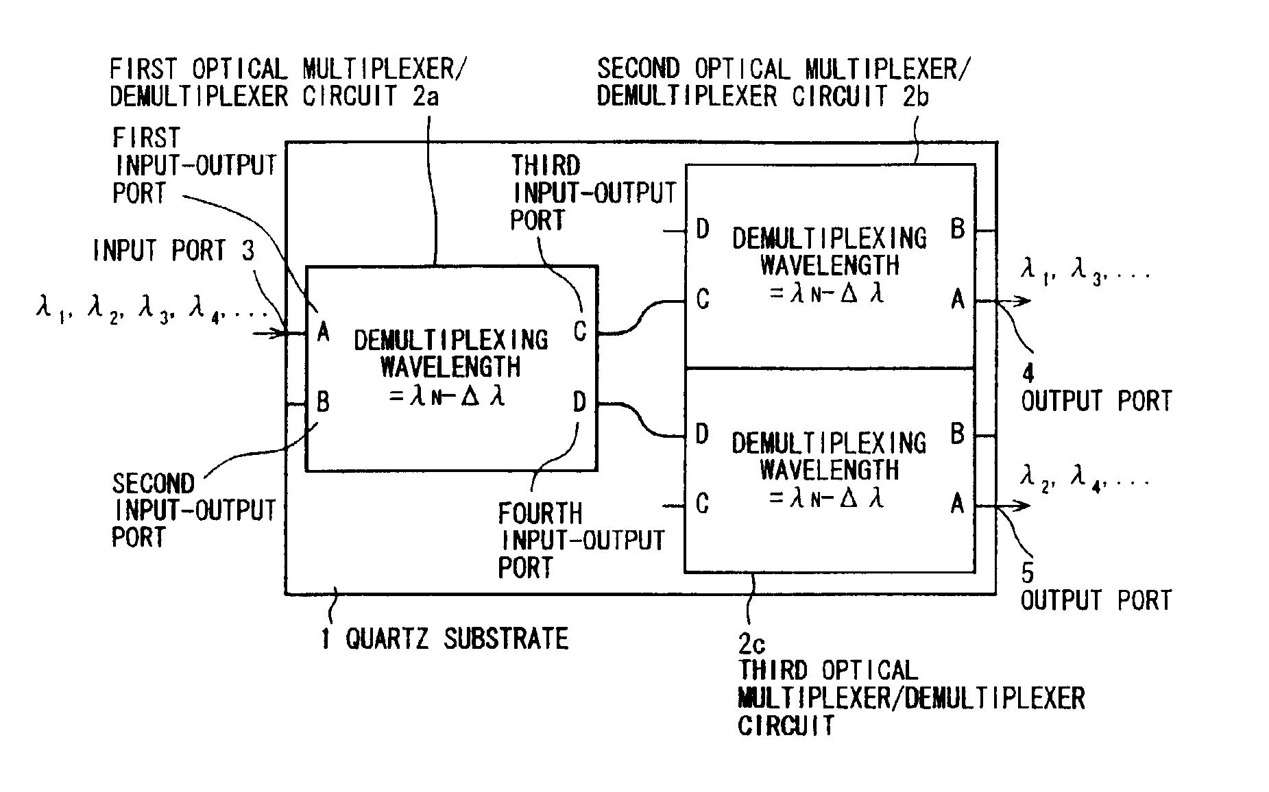
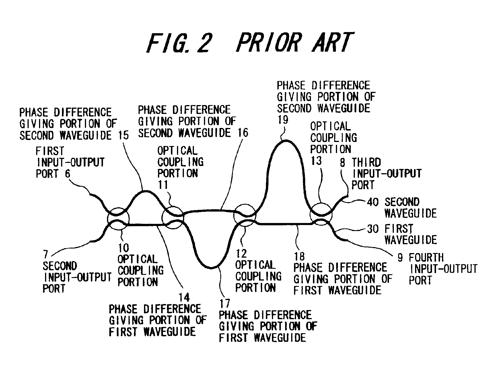
[0048]In FIG. 7(a) and FIG. 7(b), numeral 1 denotes quartz substrate, numeral 2a denotes first optical multiplexer / demultiplexer circuit, numeral 2b denotes second optical multiplexer / demultiplexer circuit and numeral 2c denotes third optical multiplexer / demultiplexer circuit, these optical multiplexer / demultiplexer circuits 2a, 2b, 2c are all formed on the quartz substrate 1. As shown in FIG. 7(b), these optical multiplexer / demultiplexer circuits 2a, 2b, 2c are constitution of Mach-Zehnder interference circuit shown in FIG. 2.

[0049]According to the above, when wavelength division multiplex signals having predetermined wavelength spacing and wavelength λ1, λ2, λ3, λ4, λ5, λ6 . . . are input through the first input-output port A, multiplex signals of odd channel wavelength λ1, λ3, λ5 . . . are output from the third input-output port C, and multiplex signals of even channel...


PUM


Abstract

A waveguide-type optical multiplexer/demultiplexer with low crosstalk characteristics and reduced wavelength dispersion is provided. A waveguide-type optical multiplexer/demultiplexer comprising, first, second and third optical multiplexer/demultiplexer circuits connected in multistage, each multiplexer/demultiplexer circuit has four input-output ports, third input-output port of first optical multiplexer/demultiplexer circuit is connected to third input-output port of second optical multiplexer/demultiplexer circuit, and fourth input-output port of first optical multiplexer/demultiplexer circuit is connected to fourth input-output port of third optical multiplexer/demultiplexer circuit, when wavelength division multiplex signals having wavelength λ1, λ2, λ3, λ4, λ5, λ6 . . . are input through first input-output port of first optical multiplexer/demultiplexer circuit, multiplex signals of odd wavelength λ1, λ3, λ5 . . . are output from first input-output port of second optical multiplexer/demultiplexer circuit, and multiplex signals of even wavelength λ2, λ4, λ6 . . . are output from first input-output port of third optical multiplexer/demultiplexer circuit.

Description

BACKGROUND OF THE INVENTION[0001]1. Field of the Invention[0002]The present invention relates to a waveguide-type optical multiplexer / demultiplexer, and more specifically to a waveguide-type optical multiplexer / demultiplexer provided with low crosstalk characteristics and reduced wavelength dispersion.[0003]2. Prior Art[0004]An interleave system which is one of wavelength multiplexing communications in next generation requires an optical multiplexer / demultiplexer provided with a function that a signal with certain channel wavelength spacing is demultiplexer to two signals with twice of said channel wavelength spacing, or contrary to this, two signals are multiplexed to one signal.[0005]FIG. 1(a) and FIG. 1(b) show an example such optical multiplexer / demultiplexer. FIG. 1(a) shows an arrangement of first to third optical multiplexer / demultiplexer circuits 21a, 21b, 21c each of which is a constituent unit of this sort of optical multiplexer / demultiplexer and has demultiplexer waveleng...

Claims


Application Information

Patent Timeline
IPC IPC(8): G02B6/12G02B6/34H04J14/02
CPCG02B6/12004G02B6/29355G02B6/2938H04J14/02G02B2006/12159
Inventor ARAI, HIDEAKICHIBA, TAKAFUMIUETSUKA, HISATOHIKAGE, MASAHIRO
Owner HITACHI CABLE
Why Eureka
Try Eureka