Compact l-shaped cylinder-cone combined tubular three-stage axial flow degassing device

a three-stage, gas-liquid separation technology, applied in liquid degasification, separation process, borehole/well accessories, etc., can solve the problems of increasing the production and maintenance costs of oil-gas field exploitation, poor compactness, low separation efficiency, etc., to achieve low liquid containing ratio, low air containing ratio, and efficient gas-liquid separation

Pending Publication Date: 2022-05-05
QINGDAO TECHNOLOGICAL UNIVERSITY
View PDF0 Cites 0 Cited by
  • Summary
  • Abstract
  • Description
  • Claims
  • Application Information

AI Technical Summary

Benefits of technology

[0034]The present invention can achieve the following technical effects: the three-stage axial flow degassing device adopts the efficient degassing technology including a vertical high speed swirling field, a horizontal rapid axial flow field and a vertical reversing scrubbing field formed by a combination of vertical tubes, horizontal tubes and T-shaped tubes, and has the characteristics of efficient gas-liquid separation, low liquid containing ratio for air after degassing and low air containing ratio for liquid after degassing; the cylindrical tube swirling generator adjusts an obliquely incident gas-containing fluid according to a spiral liquid inlet tube and a reduced spiral tooth slot, and forms a vertical high speed gas-containing swirling, and the first-stage degasser performs the first-stage segmental vertical high speed swirling degassing operation according to the cylinder-cone degassing tube, removes most of the gas phase carried by the gas-containing fluid and forms a primary gas and a primary fluid, and adjusts the primary fluid rotating at a high s

Problems solved by technology

The first type is the vertical or horizontal tank-like gas-liquid separators mainly relying on gravity settling; however, the tank-like gas-liquid separators are large in size, poor in compactne

Method used


Image

  • Compact l-shaped cylinder-cone combined tubular three-stage axial flow degassing device
  • Compact l-shaped cylinder-cone combined tubular three-stage axial flow degassing device
  • Compact l-shaped cylinder-cone combined tubular three-stage axial flow degassing device

Examples


Embodiment Construction

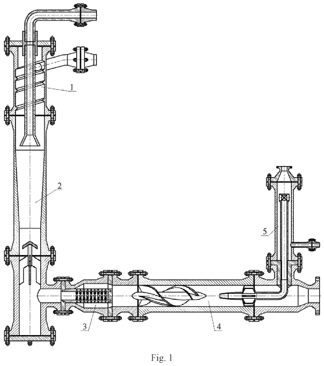
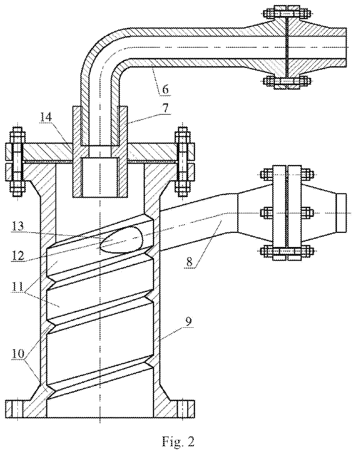
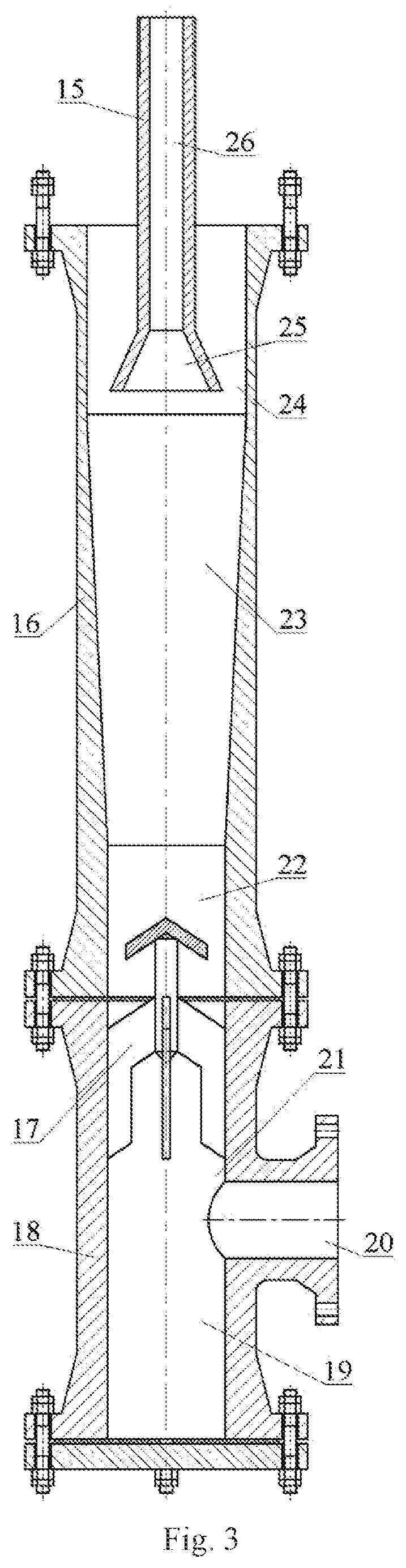
[0051]In FIG. 1, the compact L-shaped cylinder-cone combined tubular three-stage axial flow degassing device mainly comprises a cylindrical tube swirling generator 1, a first-stage degasser 2, a microporous uniform mixer 3, a second-stage degasser 4 and a third-stage degasser 5, and adopts the efficient degassing technology including a vertical high speed swirling field, a horizontal rapid axial flow field and a vertical reversing scrubbing field formed by a combination of vertical tubes, horizontal tubes and T-shaped tubes, wherein: the first-stage exhaust tube of the cylindrical tube swirling generator 1 and the third-stage exhaust tube of the third-stage degasser 5 are connected to the gas transportation manifold by means of flanges, and respectively pressurize and output separated primary gas and tertiary gas; and the second-stage liquid discharge tube of the second-stage degasser 4 and the third-stage liquid discharge tube of the third-stage degasser 5 are connected to the liqu...


PUM


Abstract

The three-stage axial flow degassing device adopts an efficient degassing technology including a vertical high speed swirling field, a horizontal rapid axial flow field and a vertical reversing scrubbing field formed by a combination of vertical tubes; the first-stage degasser performs the first-stage segmental vertical high speed swirling degassing operation, removes the gas phase carried by the gas-containing fluid, and forms a primary gas and a primary fluid; the microporous uniform mixer breaks bubbles of the primary fluid and forms a gas-liquid uniform mixed flow; the second-stage degasser performs the second-stage horizontal vane wheel swirling generating rapid axial flow degassing operation, removes the gas phase carried by the gas-liquid uniform mixed flow, and forms a secondary gas and a secondary fluid; the third-stage degasser performs the third-stage vertical reversing deep degassing operation, removes liquid phase carried by the secondary gas, and forms a tertiary gas and a tertiary fluid.

Description

TECHNICAL FIELD[0001]The present invention relates to an efficient gas-liquid separating device in the field of oil-gas field development and exploitation engineering, and particularly relates to a compact three-stage axial flow degassing device, which is L-shaped, tubular and with a combination of cylinders and cones, and the operation procedure thereof.BACKGROUND ART[0002]Efficient degassing technology of gas-liquid two-phase flow is of practical significance to the oil-gas field development and exploitation, wherein one of the main reason is that the efficient degassing technology can effectively avoid the slug flow generated during mixed transportation of gas-liquid two phases and avoid the impacts of slug flow on pipelines and equipment along the pipelines, and the other main reason is that efficient degassing technology can effectively lower the backpressure from the bottom hole during oil-gas field exploitation, thereby enhancing the oil-gas recovery rate.[0003]Conventional g...

Claims


Application Information

Patent Timeline
IPC IPC(8): B01D19/00
CPCB01D19/0068B01D19/0057E21B43/34B01D45/14B01D45/16B01D46/24B01D50/20
Inventor LIU, XINFUWANG, HUIFENGHAO, ZHONGXIANLIU, CHUNHUACHEN, JILIU, FENGWU, XIAOMINGGAO, PENGWANG, XIAOLEI
Owner QINGDAO TECHNOLOGICAL UNIVERSITY
Why Eureka
Try Eureka