Mould tool for manufacture of a wind turbine blade

a technology of wind turbine blades and moulding tools, which is applied in the manufacture of final products, climate sustainability, domestic applications, etc., can solve the problems of requiring a substantial extra amount of factory space, and achieve the effects of reducing space requirements, reducing manufacturing time, and single injection

Pending Publication Date: 2022-05-05
LM WINDPOWER +1
View PDF3 Cites 0 Cited by
  • Summary
  • Abstract
  • Description
  • Claims
  • Application Information

AI Technical Summary

Benefits of technology

[0018]It is an advantage of the present disclosure that a plurality of pre-form laminates may be provided with reduced space requirement, e.g. several pre-form laminates may be manufactured at a ground area not much bigger than a single pre-form laminate.
[0019]It is an advantage of the present disclosure that a plurality of pre-form laminates may be provided, such that a single infusion may be facilitated during manufacturing of a wind turbine blade, thereby reducing manufacturing time.
[0020]It is a further advantage of the present disclosure that it may reduce the infusion time of the wind turbine blade by facilitating the infusion process in the blade mould to be performed in one step; infusing the different fibres, e.g. glass fibres and carbon fibres, at the same time, once the one fibre type, e.g. carbon fibres, have been placed in a controlled way as the pre-form laminate to reduce or even avoid the risk of defects.

Problems solved by technology

However, a disadvantage with making pre-formed sections of laminates is that they require a substantial extra amount of factory space.

Method used


Image

  • Mould tool for manufacture of a wind turbine blade
  • Mould tool for manufacture of a wind turbine blade
  • Mould tool for manufacture of a wind turbine blade

Examples


Embodiment Construction

[0076]In the following figure description, the same reference numbers refer to the same elements and may thus not be described in relation to all figures.

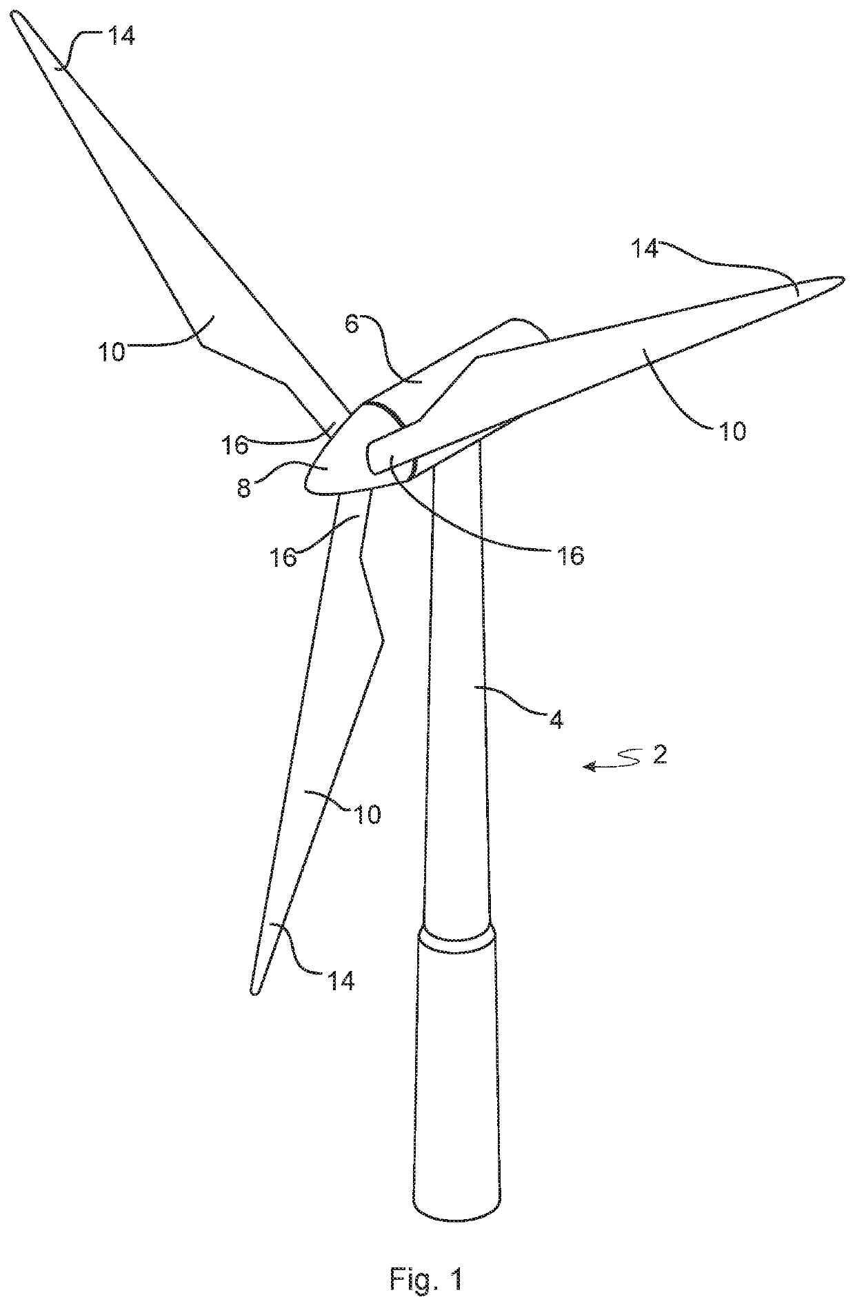
[0077]FIG. 1 illustrates a conventional modern upwind wind turbine 2 according to the so-called “Danish concept” with a tower 4, a nacelle 6 and a rotor with a substantially horizontal rotor shaft. The rotor includes a hub 8 and three blades 10 extending radially from the hub 8, each having a blade root 16 nearest the hub and a blade tip 14 furthest from the hub 8.

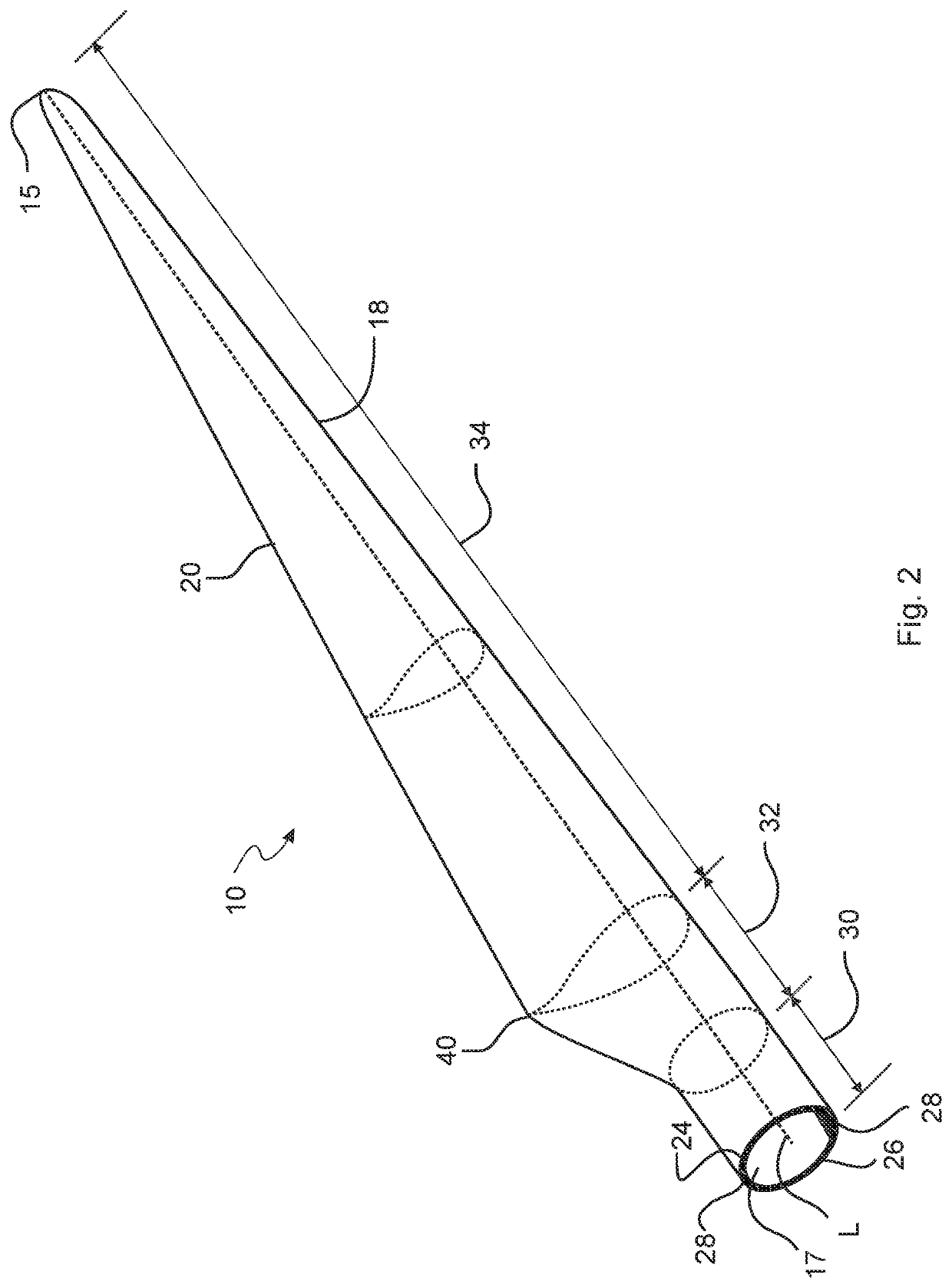
[0078]FIG. 2 shows a schematic view of an exemplary wind turbine blade 10. The wind turbine blade 10 has the shape of a conventional wind turbine blade with a root end and a tip end and comprises a root region 30 closest to the hub, a profiled or an airfoil region 34 furthest away from the hub and a transition region 32 between the root region 30 and the airfoil region 34. The blade 10 comprises a leading edge 18 facing the direction of rotation of the blade 10, when the ...


PUM

PropertyMeasurementUnit
curvatureaaaaaaaaaa
weightaaaaaaaaaa
shapeaaaaaaaaaa

Abstract

Disclosed is a mould tool for manufacturing a plurality of pre-form laminates for a laminate of a wind turbine blade, the mould tool comprising a frame, a first mould surface configured for receiving a first fabric, a second mould surface configured for receiving a second fabric, and a heating arrangement configured to heat the first mould surface and the second mould surface. The mould tool is configured to turn between a first configuration and a second configuration, wherein in the first configuration the first mould surface is facing substantially upwards, and in the second configuration the second mould surface is facing substantially upwards.

Description

FIELD OF THE INVENTION[0001]The present disclosure relates to manufacture of wind turbine blades. More specifically, the present disclosure pertains to the field of a mould tool, such as a mould tool for manufacturing a plurality of pre-form laminates for a laminate of a wind turbine blade.BACKGROUND OF THE INVENTION[0002]Wind turbine blades of fibre-reinforced polymer and in particular the aerodynamic shells of wind turbine blades are usually manufactured in moulds, where the pressure side and the suction side of the blade are manufactured separately by arranging glass fibre mats and / or other fibre-reinforcement material, such as carbon fibre, in each of the two moulds. Afterwards, one of the two halves is turned upside down and positioned on top of the other of the two halves, and the two halves are adhered together. The blade parts may be positioned on top of each other by turning and repositioning the complete half mould.[0003]A wind turbine blade may be manufactured by infusing...

Claims


Application Information

Patent Timeline
Patent Type & Authority Applications(United States)
IPC IPC(8): B29C70/44B29C33/34B29D99/00
CPCB29C70/44B29L2031/085B29D99/0028B29C33/34Y02P70/50
Inventor LUND-LAVERICK, MICHAELRAZEGHI, RAMAJESPERSEN, KLAVS
Owner LM WINDPOWER
Why Eureka
Try Eureka