Supercharge Your Innovation With Domain-Expert AI Agents!

Method and device for optically measuring distances

a distance measurement and optical measurement technology, applied in measurement devices, instruments, using reradiation, etc., can solve the problems of inability to adjust the distance measurement, the size and cost of the sensor, and the flash lidar sensor known from prior art is extremely susceptible to outside disturbance, so as to improve the accuracy of distance measurement, eliminate the need for moving parts, and improve the effect of distance measuremen

Pending Publication Date: 2022-05-05
MICROVISION
View PDF0 Cites 0 Cited by
  • Summary
  • Abstract
  • Description
  • Claims
  • Application Information

AI Technical Summary

Benefits of technology

This approach reduces the size and cost of LIDAR sensors and improves their robustness against interference, enabling reliable distance measurement for autonomous vehicle navigation without mechanical scanning mechanisms.

Problems solved by technology

The disadvantage to scanning LIDAR sensors known from prior art is that scanning is always associated with a movement of mechanical parts.
For this reason, the scanning mechanism in this type of LIDAR sensor contributes significantly to the size and costs of the sensor, since apart from the moved parts, space must also be available for the corresponding electronics for actuating the electronics assembly.
Because the entire field of view is always evaluated on the receiver side during the measuring window, the Flash LIDAR sensors known from prior art are extremely susceptible to outside disturbances.
Precisely in the area of autonomous driving, i.e., the driverless navigation of a vehicle, such a lack of robustness against targeted or inadvertent disturbance sources is unacceptable, especially from a safety standpoint.

Method used


Image

  • Method and device for optically measuring distances
  • Method and device for optically measuring distances
  • Method and device for optically measuring distances

Examples


Embodiment Construction

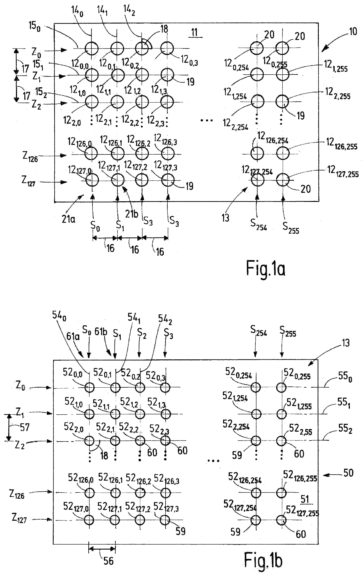
[0066]FIG. 1a presents a top view of a transmission matrix (10) of a device according to the invention. FIG. 1a depicts one side (11) of the transmission matrix (10), on which transmission elements (120,0 to 12127,255) are arranged in a regular pattern. The pattern involves a uniform grid form (13). The transmitting elements (120,0 to12127,255) can be divided into rows (Z0 to Z127) and columns (S0 to S255). The transmission matrix (10) consists of 128 rows and 256 columns of transmitting elements in all. The notation “ . . . ” on the figure denotes that additional elements of the matrix are present at this point that were not shown for the sake of clarity. In the subscripted digit in the numbering of transmitting elements (120,0 to 12127,255), the first number denotes the row of the transmission matrix (10) in which a specific transmitting element is located, while the second number in the subscripted digit quantifies the column in which this transmitting element is arranged.

[0067]T...


PUM

PropertyMeasurementUnit
distanceaaaaaaaaaa
field of viewaaaaaaaaaa
rotationaaaaaaaaaa

Abstract

An improved method for optical distance measurement is provided, in which only subsets of the transmitting elements of the transmission matrix are activated when using a transmission matrix to transmit measuring pulses and a reception matrix for receiving the latter.

Description

CROSS-REFERENCE TO RELATED APPLICATIONS[0001]This is a continuation of U.S. patent application Ser. No. 15 / 976,432, filed May 10, 2018, which is a continuation application under 35 USC 120 from International Application PCT / EP2016 / 077499, filed Nov. 11, 2016, which claims priority from European Patent Application 15194125.9, filed Nov. 11, 2015 and European Patent Application 16163529.7, filed Apr. 1, 2016, the contents of each of which are incorporated herein by reference.TECHNICAL AREA[0002]The invention relates to a method as well as to a device for optical distance measurement.BACKGROUND[0003]Optical distance measurements, in particular for use in the driverless navigation of vehicles, are based on the time of flight principle. Use is most often made of a scanning sensor, preferably of a LIDAR (abbreviation for “light detection and ranging”) sensor, which periodically sends out pulses. The pulses are reflected by objects, wherein the reflected pulses are detected. By determining...

Claims


Application Information

Patent Timeline
Patent Type & Authority Applications(United States)
IPC IPC(8): G01S7/481G01S17/10G01S17/42G01S7/484G01S7/4863G01S17/894
CPCG01S7/4815G01S17/10G01S7/4863G01S7/484G01S17/42G01S17/894
Inventor KIEHN, MICHAELKÖHLER, MICHAEL
Owner MICROVISION
Features
  • R&D
  • Intellectual Property
  • Life Sciences
  • Materials
  • Tech Scout
  • Unparalleled Data Quality
  • Higher Quality Content
  • 60% Fewer Hallucinations
Learn More