Systems and Methods for Predicting the Geometry and Internal Structure of Turbine Blades

a technology of internal structure and turbine blades, applied in the field of prediction systems and methods, can solve the problems of reducing the fitness score and reducing the efficiency of the turbine blad

Pending Publication Date: 2022-05-05
GEORGIA TECH RES CORP
View PDF0 Cites 0 Cited by
  • Summary
  • Abstract
  • Description
  • Claims
  • Application Information

AI Technical Summary

Benefits of technology

[0021]In any of the embodiments described herein, the instructions, when executed by the processor, can further cause the system to iteratively alter one or more parameters of the airfoil to reduce the fitness score.
[0022]In any of the embodiments described herein, the instructions, when executed by the processor, can further cause the system to stop iteratively altering the one or more parameters to reduce the fitness score when successive iterations reduce the fitness score less than a predetermined threshold amount.
[0023]In any of the embodiments described herein, the instructions, when executed by the processor, can further cause the system to display the geometrical representation of the turbine blade.

Problems solved by technology

Blades for turbines installed in the early 2000s are nearing the end of their 20-year design lives, and the need to recycle the blades has become a well-recognized problem.
Advancements in turbine technology have rendered these turbines functionally obsolete.
Recycling of the steel and copper that make up most of the turbine mass is well understood, but the potential for recycling or re-purposing the composite materials has not been addressed.
Efforts to use the ground waste in the production of new FRP composites shows that the inclusion of recycled materials dramatically decreases the mechanical properties of the material.
A problem exists, however, in that the specific geometrical structure of these turbines are unknown.

Method used


Image

  • Systems and Methods for Predicting the Geometry and Internal Structure of Turbine Blades
  • Systems and Methods for Predicting the Geometry and Internal Structure of Turbine Blades
  • Systems and Methods for Predicting the Geometry and Internal Structure of Turbine Blades

Examples


Embodiment Construction

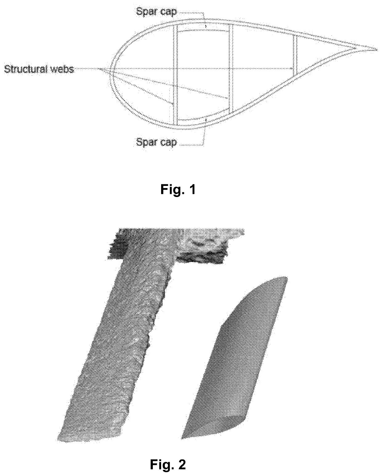
[0030]To facilitate an understanding of the principles and features of the present invention, various illustrative embodiments are explained below. To simplify and clarify explanation, the invention is described below as applied to predicting the geometry of a wind turbine blade. One skilled in the art will recognize, however, that the invention is not so limited. Instead, as those skilled in the art would understand, the various embodiments of the present invention also find application in other areas, including, but not limited to, hydro turbine blades, propellers, impellers, and the like.

[0031]The components, steps, and materials described hereinafter as making up various elements of the invention are intended to be illustrative and not restrictive. Many suitable components, steps, and materials that would perform the same or similar functions as the components, steps, and materials described herein are intended to be embraced within the scope of the invention. Such other compone...


PUM


Abstract

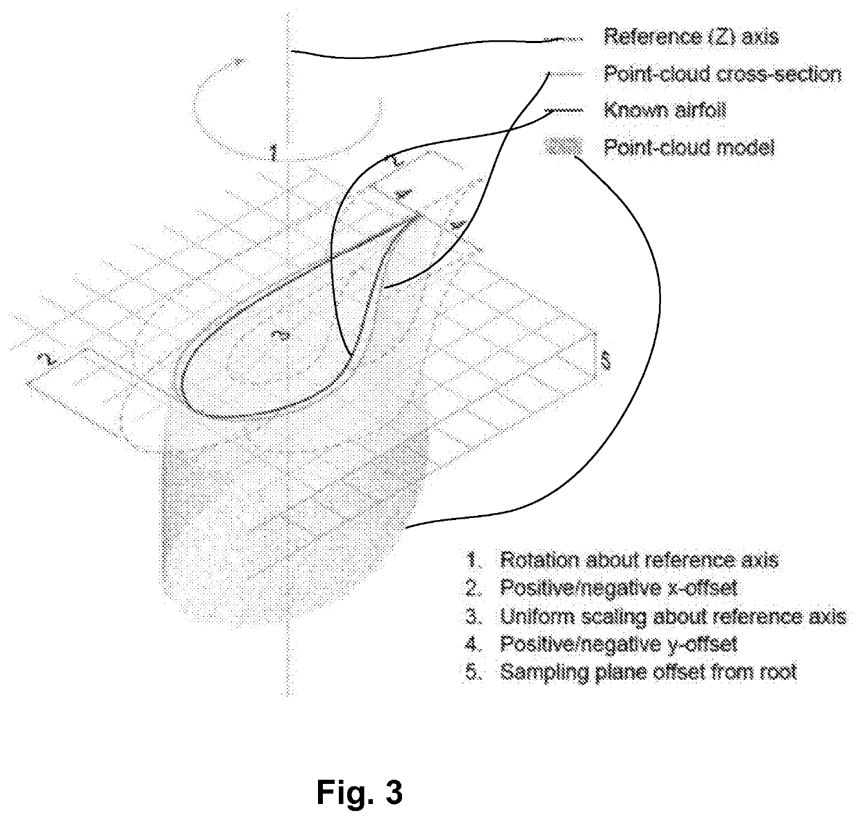
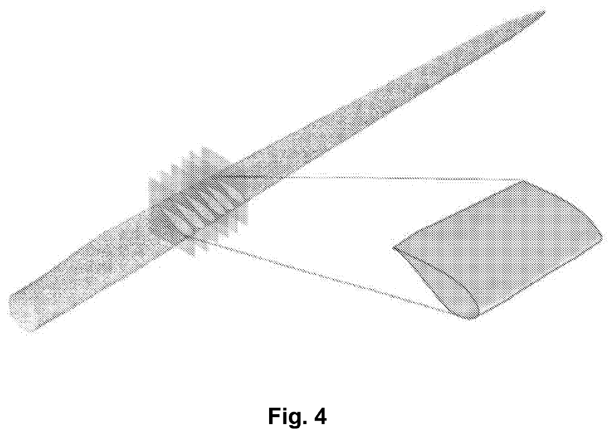
An exemplary embodiment provides a method of predicting a geometry of a turbine blade, comprising: obtaining a point cloud of the turbine blade, the point cloud comprising a plurality of points corresponding to locations on an external contour of the turbine blade; generating an external mesh for the turbine blade based on point cloud; defining a reference axis along the length of the blade; generating a plurality of sampling planes along the length of the reference axis, each sampling plane being normal to the reference axis and having a shape defined by portions of the mesh intersecting the sampling plane; for each of the plurality of sampling planes, matching the sampling plane to an airfoil profile in a database of known airfoil profiles; and creating a geometrical representation of the turbine blade by placing the airfoils on the reference axis and connecting the perimeter of each of the airfoils.

Description

CROSS-REFERENCE TO RELATED APPLICATIONS[0001]This application claims the benefit of U.S. Provisional Application Ser. No. 62 / 811,681, filed on 28 Feb. 2019, which is incorporated herein by reference in its entirety as if fully set forth below.FEDERALLY SPONSORED RESEARCH STATEMENT[0002]This invention was made with government support under Grant No. 1701413, awarded by the National Science Foundation. The government has certain rights in the invention.TECHNICAL FIELD OF THE INVENTION[0003]The various embodiments of the present disclosure relate generally to predictions systems and methods. More particularly, the various embodiments of the present invention are directed to systems and methods for predicting the geometry and internal structure of turbine blades.BACKGROUND OF THE INVENTION[0004]The production of wind energy worldwide has increased twenty-fold since 2001. Almost all of this energy is generated by three-bladed wind turbines with fiber reinforced polymer (FRP) (e.g., plast...

Claims


Application Information

Patent Timeline
Patent Type & Authority Applications(United States)
IPC IPC(8): G06F30/17G06F30/20G06Q10/00
CPCG06F30/17G06Q10/30G06F30/20G06T17/20F05D2260/80F01D5/282F01D5/141F05D2300/603G06T2210/56Y02W90/00
Inventor GENTRY, RUSSELLTASISTRO-HART, BENJAMIN
Owner GEORGIA TECH RES CORP
Why Eureka
Try Eureka