Method of predicting liquid regions and vapor regions in bipolar plates of a fuel cell

a fuel cell and bipolar plate technology, applied in the direction of fuel cells, electrical appliances, electrochemical generators, etc., can solve the problems of inefficient fc stack performance, narrow or completely blocked cooling channels, and inconvenient fc stack cooling, so as to reduce the size of the fc, minimize flooding, and maximize performance

Pending Publication Date: 2022-05-05
TOYOTA MOTOR ENGINEERING & MANUFACTURING NORTH AMERICA
View PDF2 Cites 0 Cited by
  • Summary
  • Abstract
  • Description
  • Claims
  • Application Information

AI Technical Summary

Benefits of technology

[0010]In accordance with one or more embodiments, one or more methods are implemented where one or more regions of the air layer of an FC plate is inhibited by saturation or flooding by the water produced. A reiterative method determines one or more regions in the microchannels of the air layer where the oxygen concentration is less than a predetermined threshold concentration where densities and dynamic viscosities of water in the microchannels are applied thereto, while repetitively executing an algorithm until a convergence occurs. Maps are generated illustrating phase composition and oxygen distribution by the application or absence of the two-phase model. The model-determined conditions are then used to optimize design of the FC plate to minimize flooding while maximizing performance.
[0011]In accordance with one or more embodiments, a FC comprises bipolar plates having multi-scale, multi-layer Turing-pattern microstructures for efficient fluid distribution. Such Turing-patterned microstructures provide for a reduction in size of the FC. Such efficient fluid distribution yields enhanced operational performance in the FC stack by facilitating more uniform cooling of the MEA at the coolant layer. Such uniform cooling, in turn, facilitates more uniform reactions at the MEA, and thus, maximizes the generation of electricity by the FC stack.

Problems solved by technology

In such configurations, however, the coolant channels are very narrow or completely blocked, while in other regions the coolant channels are wide and open.
This may lead to non-uniform cooling throughout the FC stack, and consequently, inefficient FC stack performance.
An additional problem with FC performance is liquid saturation (i.e., flooding) as a result of water condensation produced as a byproduct of the reaction during the production of electricity by the FC.
The undesirable build-up of water, causing a phenomena called flooding, can occur in the microchannels of the air layer, thereby blocking, restricting, and / or limiting air flow and / or hydrogen flow.
Water condensation at the air layer makes oxygen less available to generate electricity, thus making the performance of the FC becomes less reliable.
The use of inverse design methods for designing FC bipolar plates, however, has been limited to a single layer configuration.
Contemporary design methods generally use explicit topology optimization, which are inevitably expensive in computation.

Method used


Image

  • Method of predicting liquid regions and vapor regions in bipolar plates of a fuel cell
  • Method of predicting liquid regions and vapor regions in bipolar plates of a fuel cell
  • Method of predicting liquid regions and vapor regions in bipolar plates of a fuel cell

Examples


Embodiment Construction

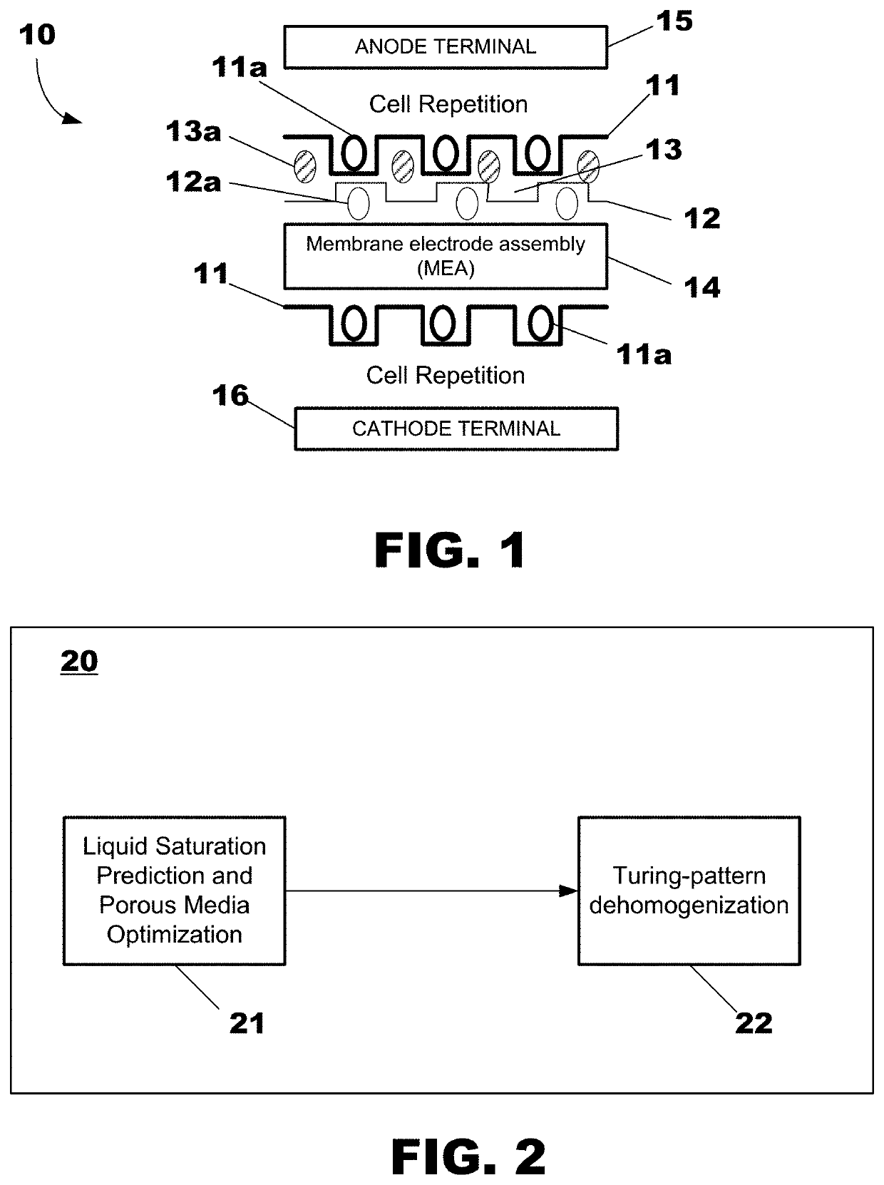
[0041]As illustrated in FIG. 1, a fuel cell 10 comprises a first bipolar plate comprising a first stamped metal plate or layer 11 (serving as the anode), a second stamped metal plate or layer 12 (serving as the cathode), and an MEA membrane 14 interposed therebetween. An anode terminal electrode 15 is electrically connected to the anode 11, while a cathode terminal electrode 16 is electrically connected to the cathode 12.

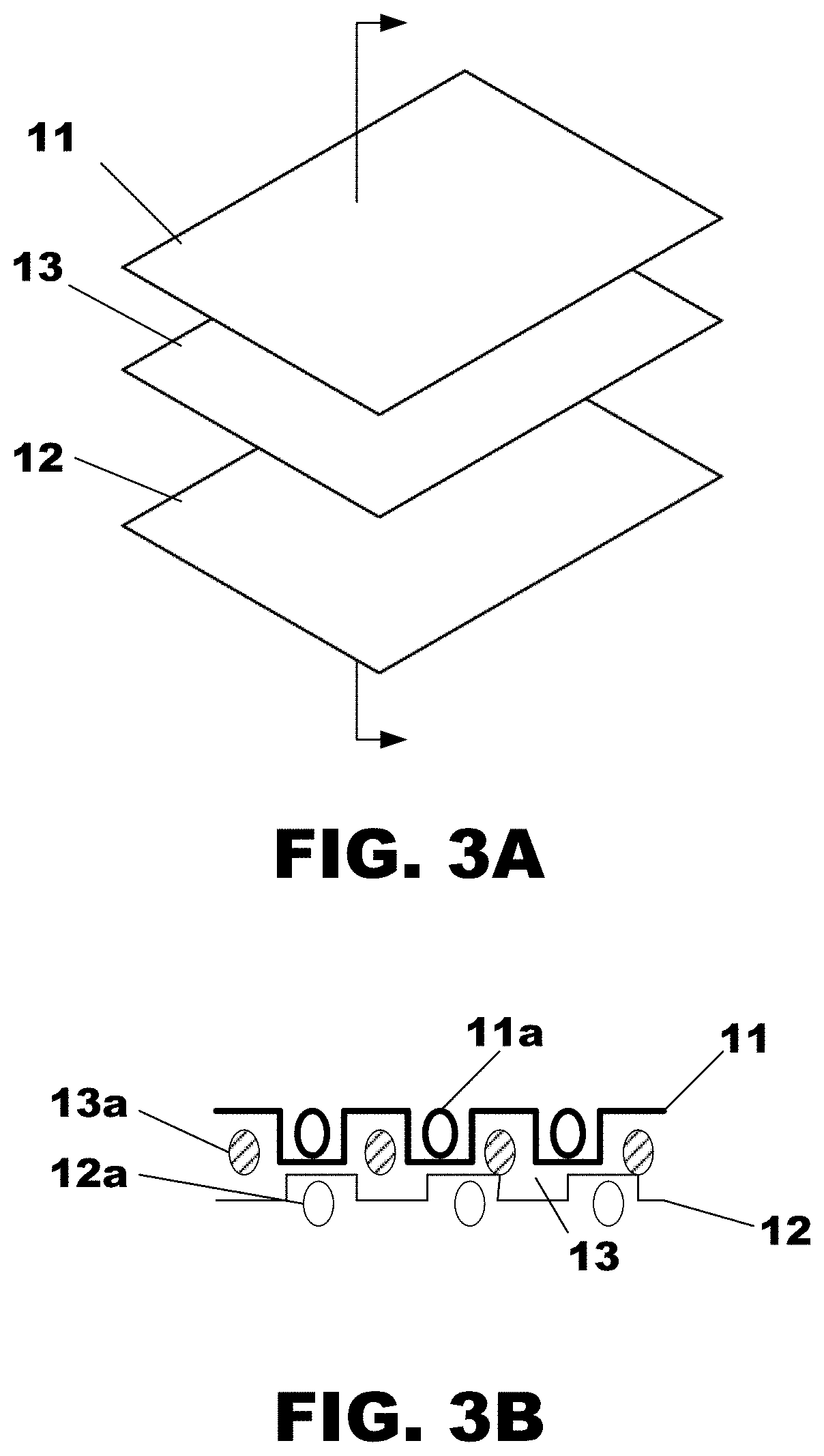
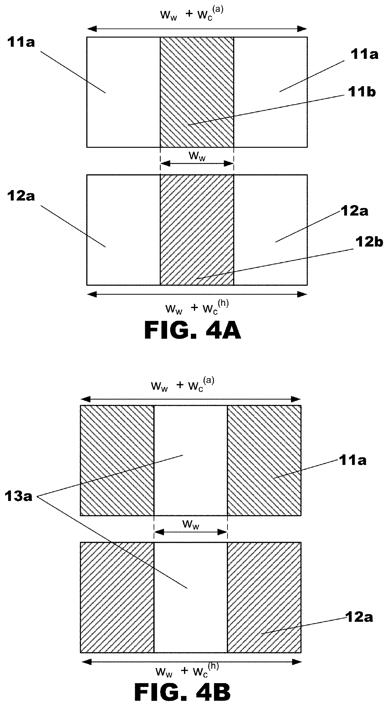
[0042]The first stamped metal plate or layer 11 has a plurality of independently formed air fluid flow networks 11a, and the second stamped metal plate or layer 12 has a plurality of independently formed hydrogen fluid flow networks 12a. Through the stacking of the first stamped metal plate 11 and the second stamped metal plate 12, a coolant layer 13 comprising a plurality of coolant flow networks 13a is defined. In this way, the coolant fluid flow network configuration 13a is dependent upon the independently-formed air networks 11a and hydrogen channels 12a.

[0043]...


PUM

PropertyMeasurementUnit
microstructuresaaaaaaaaaa
concentrationaaaaaaaaaa
permeabilityaaaaaaaaaa

Abstract

A method of designing a fuel cell includes executing one or more programs on one or more computing devices having one or more processors to predict a location of one or more liquid regions and one or more vapor regions in microchannels at an air layer of a plate of the fuel cell. Based on the prediction, fluid flow networks for the air layer, a hydrogen layer, and a coolant layer of the fuel cell are simultaneously optimized via homogenized flow optimization. In response to the results of the homogenized flow optimization, one or more multi-scale Turing-patterned microstructures are generated for the air layer and the hydrogen layer. One or more multi-scale Turing-patterned microstructures are generated for the coolant layer by stacking the air layer and the hydrogen layer.

Description

TECHNICAL FIELD[0001]Embodiments relate generally to one or more methods for designing a fuel cell using a model to predict a location of liquid regions and vapor regions in channels of a plate of the fuel cell.BACKGROUND[0002]Hydrogen fuel cell (FC) technology has been utilized widely in a variety of stationary and non-stationary applications, e.g., space transport, satellites, motor vehicles, power generation, and electronics. The FC device converts chemical potential energy into electrical energy.[0003]A FC stack generally comprises hundreds of FCs arranged in a stack formation. Each individual FC in the stack may have a structure comprising a membrane electrode assembly (MEA) which is interposed between plates representing electrodes The MEA is as a proton exchange membrane (PEM) cell having sides coated with a catalyst for the hydrogen oxidation (anode) and oxygen reduction (cathode). Gas diffusion layers (GDL) are used to deliver the reactant fuels to the electrodes from bipol...

Claims


Application Information

Patent Timeline
Patent Type & Authority Applications(United States)
IPC IPC(8): H01M8/2404H01M8/0267H01M8/0258
CPCH01M8/2404H01M8/0258H01M8/0267Y02E60/50H01M8/04291H01M8/04835H01M8/04992
Inventor ZHOU, YUQINGDEDE, ERCAN M.
Owner TOYOTA MOTOR ENGINEERING & MANUFACTURING NORTH AMERICA
Why Eureka
Try Eureka