
Electrolytic cell

a technology of electrolysis cell and electrolysis process, which is applied in the direction of cells, electrolysis components, electrolysis processes, etc., can solve the problems of large conversion cost and large amount of energy consumed, and achieve the effect of complex manufacturing of resilient means

Inactive Publication Date: 2003-03-13
PERMASCAND
View PDF7 Cites 6 Cited by
  • Summary
  • Abstract
  • Description
  • Claims
  • Application Information

AI Technical Summary

Benefits of technology

[0008] It has been surprisingly found that the present invention can provide advantageous operation to a retrofitted gas diffusion electrode cell. The invention enables a simple retrofitted gas diffusion electrode cell by converting a conventional hydrogen evolving cathode cell at a low cost. The invention further ascertains low cell voltage and stable operation. It can thus enable homogeneous connection between the separator and the gas diffusion electrode. The relatively short distance between the separator and the gas diffusion electrode minimises the cell voltage and makes the cell operation almost as energy-saving as a zero gap cell. The invention also ascertains a safe operation minimising flooding of electrolyte in the cathode compartment.
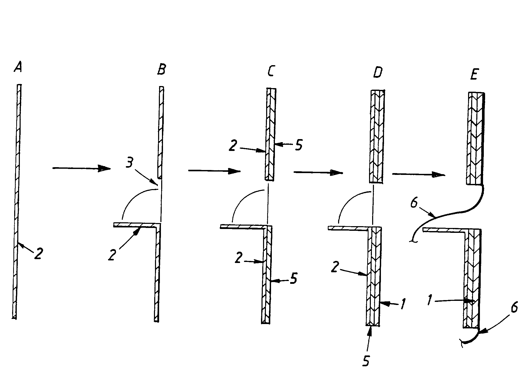
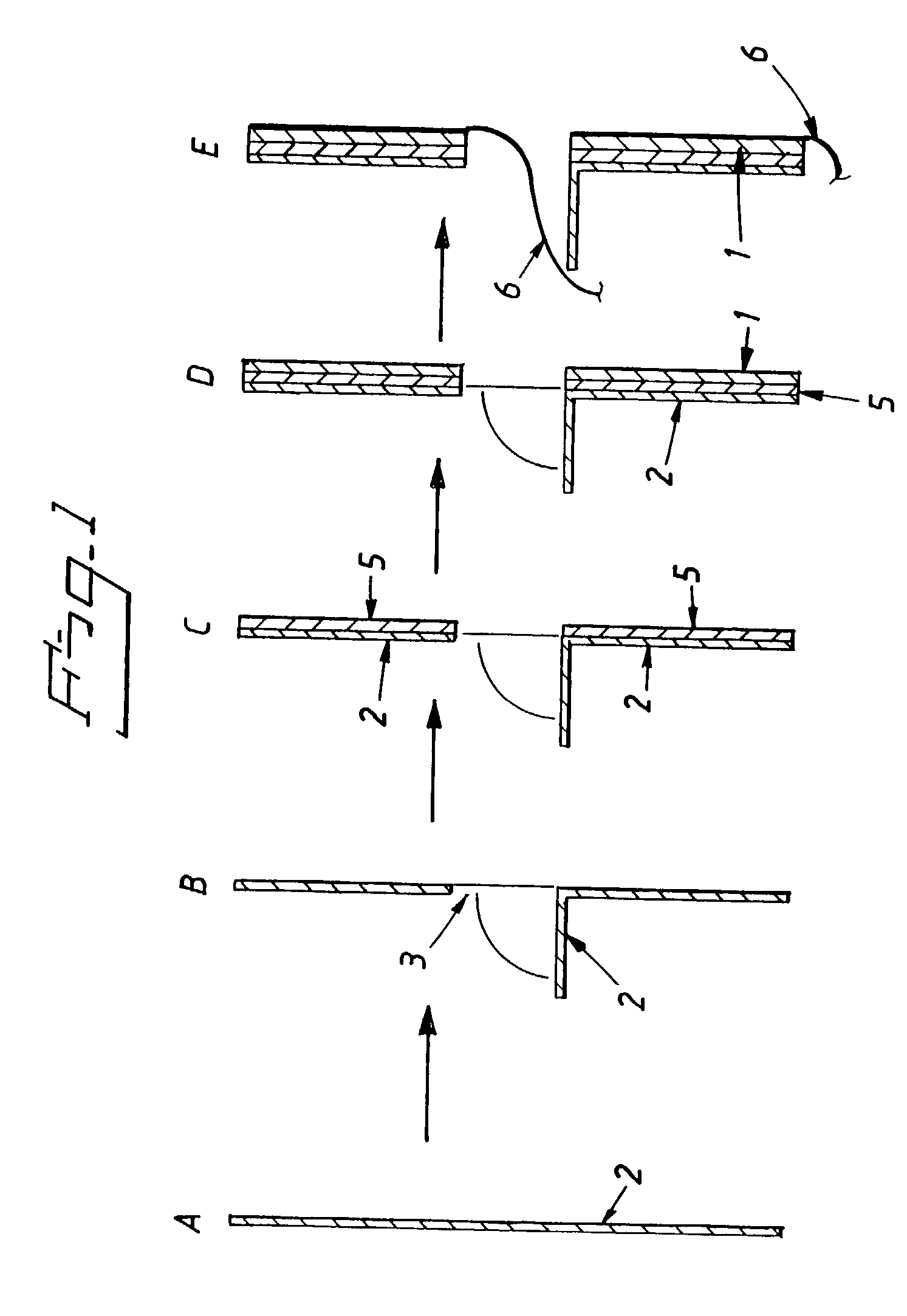
[0014] By the term "electrolyte layer" is meant a hydrophilic layer capable of retaining electrolyte substantially deriving from the anode compartment, e.g. in the production of sodium hydroxide in which process sodium ions carrying water molecules are transported over the separator. The electrolyte layer is arranged between the separator and the gas diffusion electrode and suitably comprises a carbon cloth, e.g. a graphite cloth, nonwoven cloth filter of fluorinated resins, ceramic fiber cloth, ceramic fluor resin cloth, or a ceramic coated carbon cloth retaining the electrolyte between the gas diffusion electrode and the separator. The carbon cloth suitably extends through the slits made in the cathode members as further described herein. The electrolyte can in this way be drained from the electrolyte layer avoiding flooding of the gas diffusion electrode. The electrolyte can thus leave the cathode compartment in a controlled way at the oxygen-containing gas-supplied side of the cathode compartment.
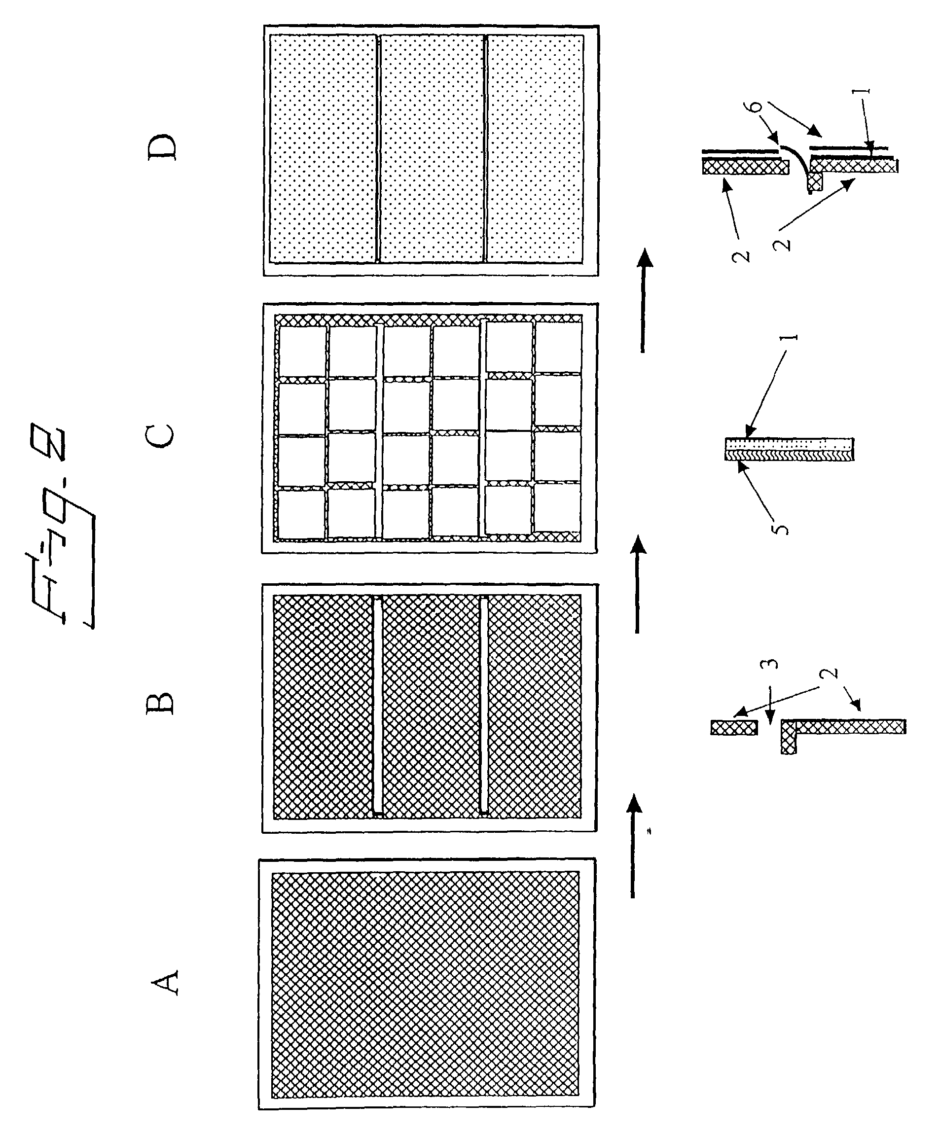
[0020] According to one embodiment, the method involves arranging resilient means between the existing hydrogen evolving cathode and the gas diffusion electrode. It has been found that resilient means contribute to a more homogeneous contact between the gas diffusion electrode and the electrolyte layer. Furthermore, it has been found that the resilient means can secure safe retention of electrolyte between the separator and the gas diffusion electrode. The resilient means can also play the role of current distributor. Such resilient means may be selected from expanded mesh, wire net, springs, ribs, elastic louvers, perforated plates, metal foams or mixtures thereof, suitably comprising plural members made of a porous metal arranged so that gas and electrolytes thereby easily can be supplied and removed from the gas diffusion electrode. Preferably, the resilient means have substantially the same dimensions as the gas diffusion electrode or plural members thereof so that the resilient means can be individually fitted thereto. The dimensions of the resilient means connected to the gas diffusion electrode are suitably not larger than 40 cm, because the distance to the separator can in those cases be inhomogeneous, which can lead to inhomogeneous current distribution. In case the dimensions are shorter than 10 cm, the manufacturing of the resilient means may be very complicated. The dimensions of the resilient means are suitably from about 10 to about 40 cm, preferably from about 10 to about 30 cm, and most preferably from about 20 to about 25 cm.

Problems solved by technology

The electrolytic production of alkali metal hydroxides is today of considerable importance, although a large amount of energy is consumed in the electrolysis processes.
However, this conversion requires a large reconstruction cost due to the complicated cathode chamber structure needed for controlling the pressure arisen between the gas diffusion electrode and the ion exchange membrane.

Method used


Image

  • Electrolytic cell
  • Electrolytic cell
  • Electrolytic cell

Examples


example 1.1

[0041] The same retrofitting as in example 1 was performed but with one piece of carbon cloth instead of three pieces. Electrolysis was performed under the same conditions as in example 1, which resulted in an increase in cell voltage from the initial value of 2 V to 2.4 V after 100 hours. The cell was opened after 150 hours of electrolysis. Flooding of the lower portion of the cell was observed.

example 1.2

[0042] Similar retrofitting as in example 1 was performed but without a current distributor between the existing cathode and the gas diffusion electrode members. Electrolysis was performed under the same conditions as in example 1. The cell voltage was 2.2 V at a current density 30 A / dm.sup.2. Even though the current density was lowered to 5 A / dm.sup.2, the cell voltage was maintained at 2.2 V. No reduction of the cell voltage was observed after 1000 hours of operation. The cell was opened after 1000 hours of operation and partially dry portions on the surface of the gas diffusion electrode were found. This resulted from inhomogeneous contact between the gas diffusion electrode and the electrolyte layer.

example 2

[0043] A gas diffusion electrode was prepared by coating silver paste on a silver expanded mesh. PTFE was used as binder. Sintering was performed first at 150.degree. C. for 20 minutes and then at 250.degree. C. for 30 minutes. Silver powder having a particle size of 10 to 100 nm was mixed with 20 wt % of a Nafion.TM. solution and subsequently applied on the silver paste followed by further sintering at 140.degree. C. The obtained gas diffusion electrode members were attached as in example 1. The whole cell assembly used was the same as of example 1 except the gas diffusion electrode. Electrolysis was performed under the same conditions as of example 1 and a cell voltage around 2 V at a current density of 30 A / dm.sup.2 was obtained. The cell voltage was kept at around 2 V even after 2000 hours of operation.


PUM

PropertyMeasurementUnit
thickaaaaaaaaaa
distanceaaaaaaaaaa
voltageaaaaaaaaaa

Abstract

The present invention relates to a retrofitted electrolytic cell and a method for retrofitting an electrolytic cell comprising an anode and a cathode compartment, a separator partitioning the compartments, said cathode compartment comprising a hydrogen evolving cathode. The method comprises making at least one substantially horizontal slit in the hydrogen evolving cathode resulting in plural cathode members, bending the edge of at least one cathode member at the slit away from the separator, arranging a gas diffusion electrode to the cathode members on the side facing the separator, and arranging an electrolyte layer to the gas diffusion electrode. The invention also relates to the use of a retrofitted electrolytic cell.

Description

[0001] The present invention relates to a method for retrofitting a conventional hydrogen evolving cathode cell to a gas diffusion electrode cell. The invention also relates to the retrofitted electrolytic cell and the use thereof.[0002] The electrolytic production of alkali metal hydroxides is today of considerable importance, although a large amount of energy is consumed in the electrolysis processes. Many attempts have been made to lower the energy consumption, e.g. by using a gas diffusion cathode in the electrolytic cell which today is believed to have the highest capability of saving electric energy and lower the production costs.[0003] If the production of sodium hydroxide from brine in a conventional hydrogen evolving cathode cell in which the electrolytic reaction (1) occurs instead is performed in a gas diffusion cathode cell, the reaction (1) is replaced by reaction (2).2NaCl+2H.sub.2O.fwdarw.Cl.sub.2+2NaOH+H.sub.2, E.sub.0=2.21 V (1)2NaCl+{fraction (1 / 20)}.sub.2+H.sub.2O...

Claims


Application Information

Patent Timeline
Patent Type & Authority Applications(United States)
IPC IPC(8): C25B1/46C25B9/19
CPCC25B1/46C25B9/08C25B11/035C25B9/19C25B11/031
Inventor SHIMAMUNE, TAKAYUKI
Owner PERMASCAND
Learn More