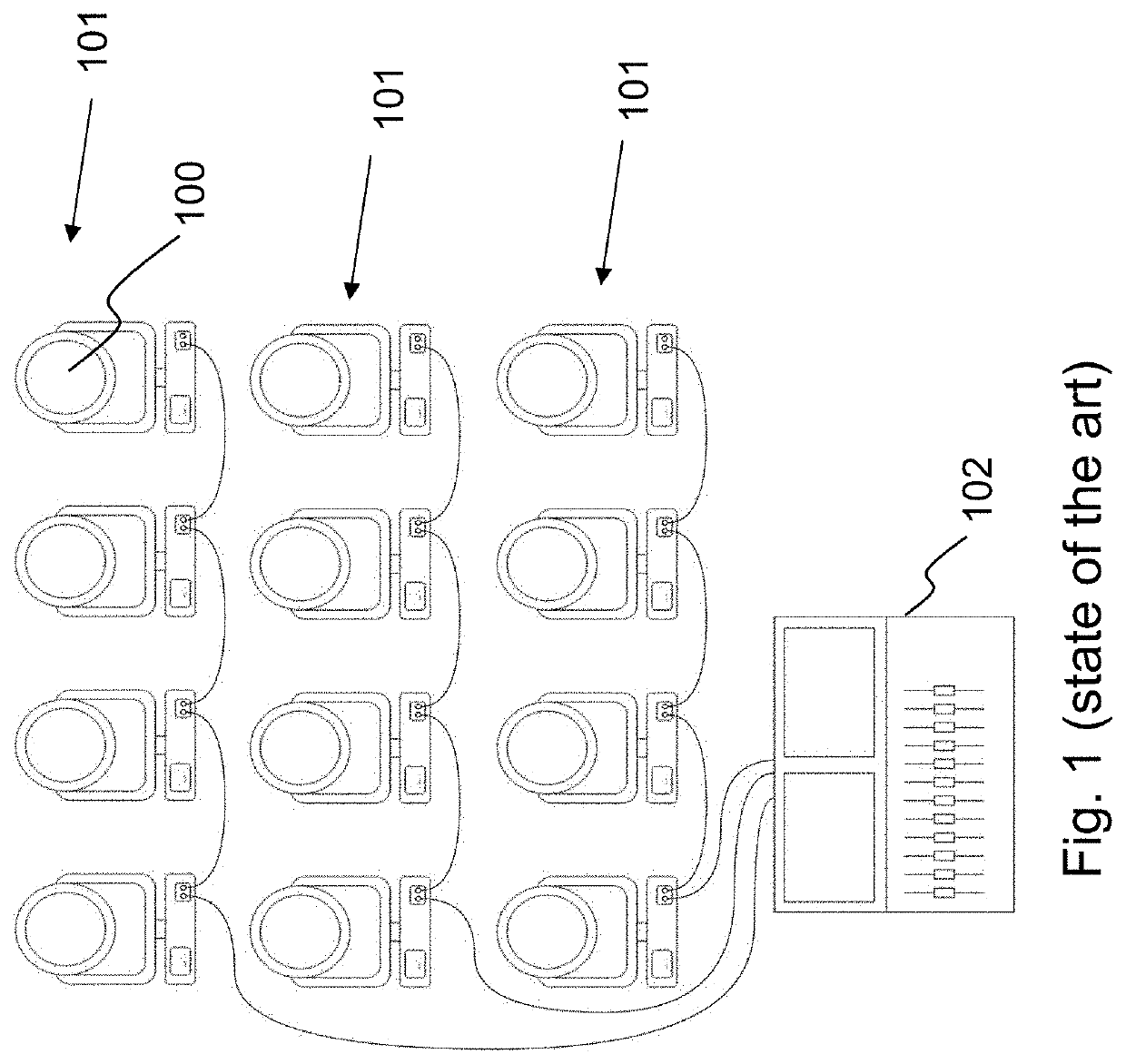
These installations are often rather extensive, with hundreds of connected devices.
Users of such professional installations are often faced with the problem that a different installation is set up for each new event or show, for which a new setup and configuration of the communication network is required in each case.
Once the entertainment installation is in operation, users are faced with problems arising in the transfer of data, caused by interruptions in the power supply or faulty connections, as a result of which the control of the devices is disrupted.
Ultimately, given the large number of connected devices, it is not straightforward to detect whether and where a fault has occurred.
Since DMX is limited by the standard to 512 channels, this is not sufficient to connect all connected devices to one DMX controller if the sum of the channels required by the devices is greater than 512.
Such a conventional DMX solution comes with a number of limitations.
This limit of 512 channels and the use of various universes to overcome it results in substantial complexity during the preparation, connection and setup of the installation.
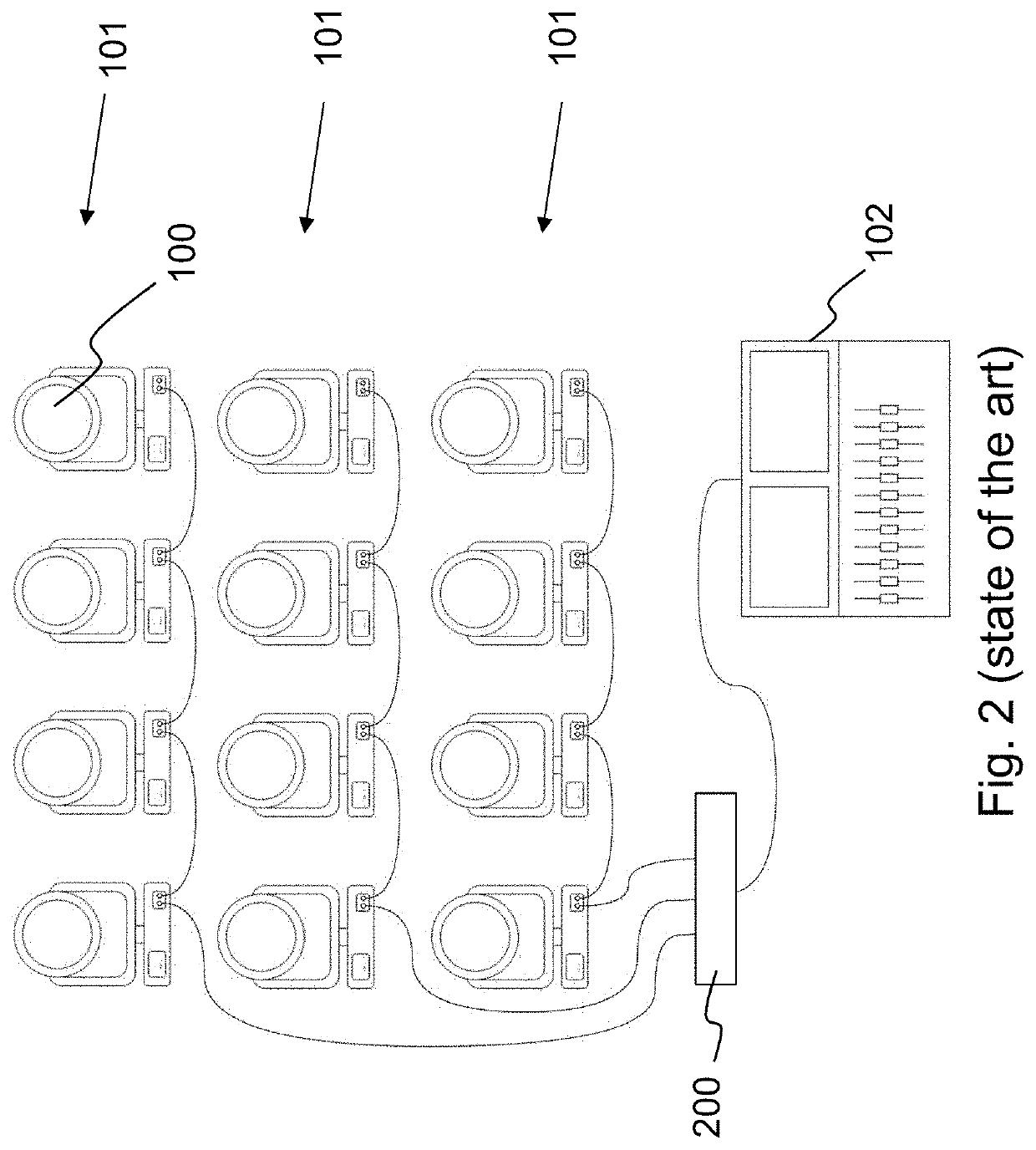
With each hop in the network, a
delay results due to the handling of the packet in this hop.
With a plurality of hops in the network, the
residence time will be multiplied by the number of hops and accumulated
residence time results, which leads to a synchronization problem between the first and the last hop in the network.
In addition to the fact that, due to the 512-channel limit, setting up a conventional DMX solution is complicated, configuring such a solution is also laborious.
This means that problems may arise with one device reacting in an unintended manner to control meant for another device, due to the overlap in the range over which they listen for the DMX
signal.
In an offline context, which applies to most controllers, this complicates the patching process.
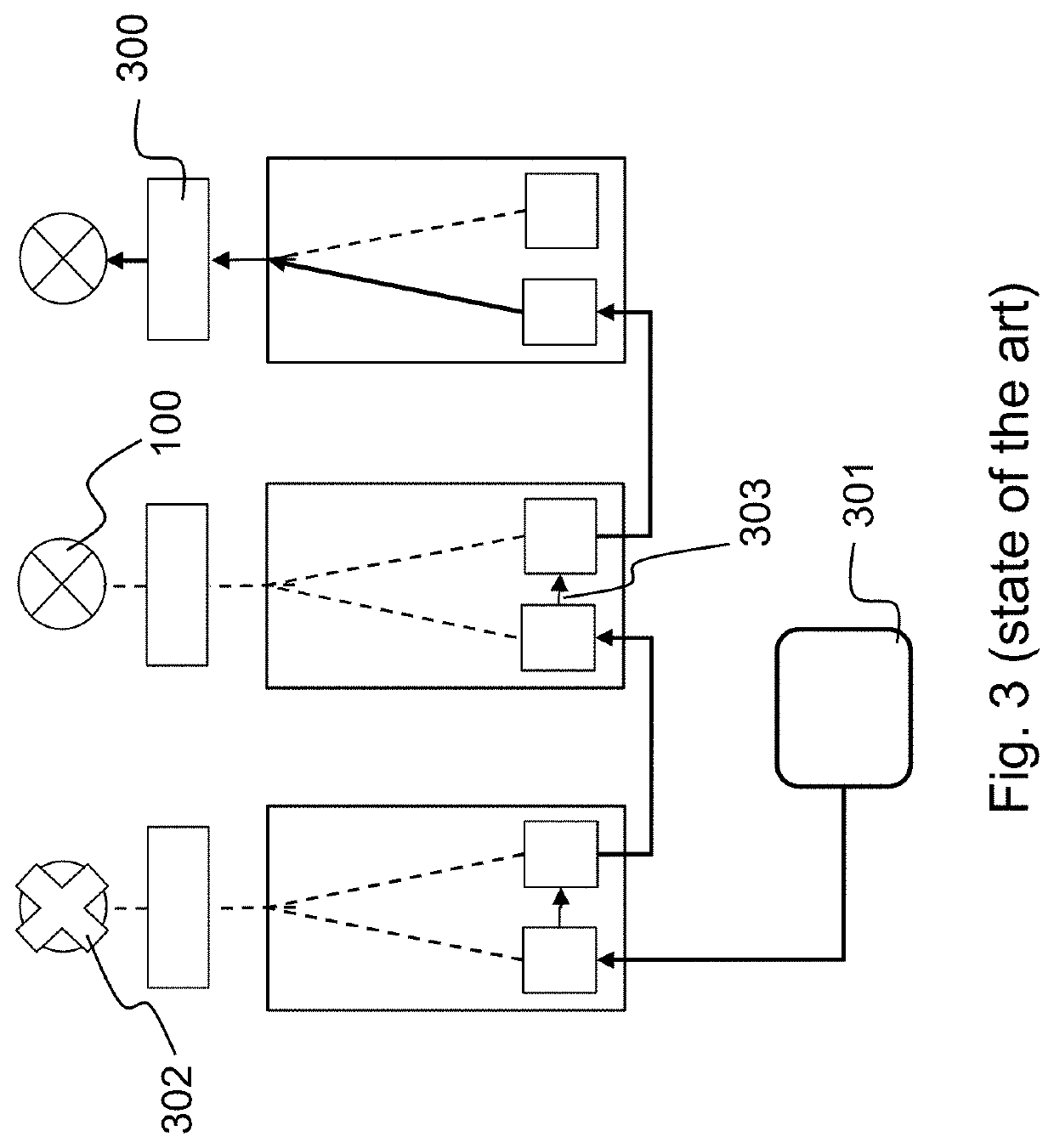
Another limitation of the conventional DMX solution lies in the area of reliability or redundancy.
However, in the case of a faulty cable or another problem, other than the abovementioned power interruption, those devices which are located “after” the problem on the line will receive a faulty
signal or no
signal at all.
Given that all devices are connected in succession on the DMX line, there is no possibility of reaching the connected devices via an alternative
route.
Consequently, the conventional DMX solution does not provide completely redundant control, since data transfer cannot be guaranteed in the event of problems such as a faulty cable.
The final limitation with the conventional DMX solution arises as a result of the use of the RS-485 standard
as interface, which is half-duplex.
This limitation results in an extra protocol being needed in order to provide two-way communication.
However, RDM comes with a number of limitations.
First, RDM is a very slow protocol, and it has low bandwidth.
It is also completely based on timing and therefore difficult to implement.
Because of this, the distribution of information on what is happening in the connected devices is still very limited, so that it is difficult for the user to
gain insight into whether and where there are problems in the network.
These
Ethernet-based solutions also have a number of limitations.
This can present a barrier in practice.
In addition, it is not possible with these
Ethernet-based solutions to provide the connected devices with redundant control.
Ethernet is full-duplex and daisy-chaining with devices connected in series is not possible in this case.
This problem does not occur when using a star topology, but the greatest drawback of a star topology is that it requires extra cabling to the hub of the star.
Lastly, the known Ethernet-based solutions have limitations in terms of the communication protocol used.
The above shows that there is currently no solution in the prior art which allows straightforward setup and completely redundant control.
In addition, none of the existing solutions afford the user the possibility of being able to consult information regarding the network in a straightforward manner, information such as how the devices are physically connected to one another or where problems in the network are occurring.
This complicates both the initial configuration of the network and the solving of problems while the installation is in operation.

