
Oil seal distributing mechanism for vibrator bowl

Pending Publication Date: 2022-05-12
ZHEJIANG LINIX MOTOR
View PDF0 Cites 0 Cited by
  • Summary
  • Abstract
  • Description
  • Claims
  • Application Information

AI Technical Summary

Benefits of technology

The present invention is a mechanism for distributing oil seals in a machine. The mechanism includes a track for moving the oil seal forward, a distributor for supporting the oil seal, a force applying mechanism for suspending or dropping down the oil seal, and a fixed tube for stabilizing the air outlet point. The mechanism can also include a notch on the hopper for easy feeding of oil seals and a fixed bracket for guiding the oil seals. The technical effects of the mechanism include improved oil seal distribution, reduced labor intensity of workers, and efficient production.

Problems solved by technology

In the prior art, oil seals are often conveyed in an orderly and directional arrangement through a vibrator bowl or disk, but existing vibrator bowls are incapable of determining the front and back of oil seals or distributing oil seals.

Method used


Image

  • Oil seal distributing mechanism for vibrator bowl
  • Oil seal distributing mechanism for vibrator bowl
  • Oil seal distributing mechanism for vibrator bowl

Examples


Embodiment Construction

[0016]The present invention will be further described below with reference to accompanying drawings by embodiments.

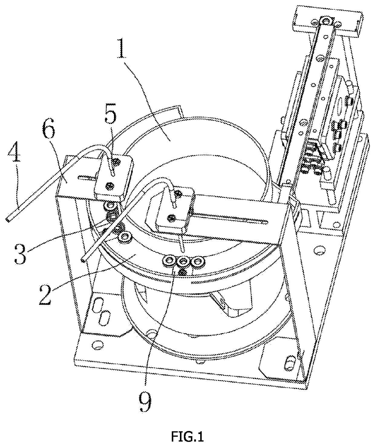
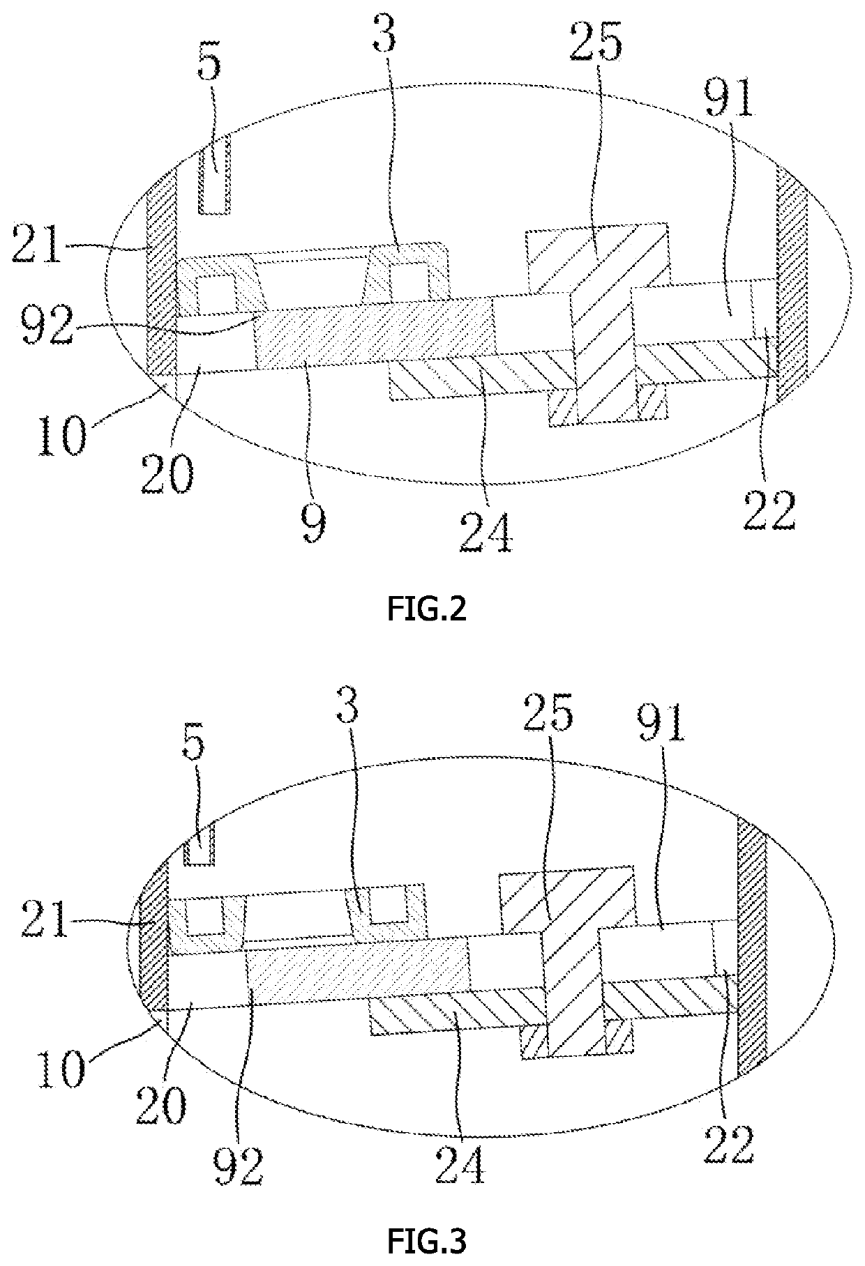
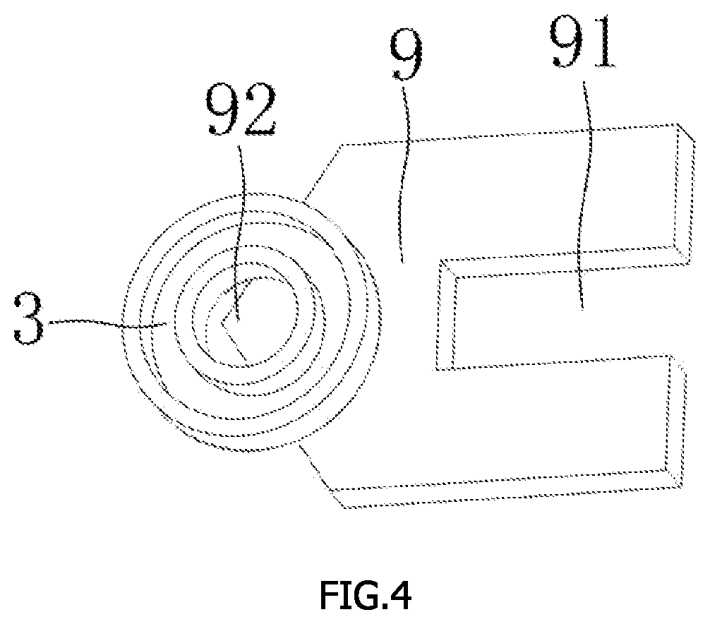
[0017]As shown in FIGS. 1 to 4, an oil seal distributing mechanism for a vibrator bowl is provided in the present invention. A feeding track 2 of the vibrator bowl / disk 1 includes a left side plate 21 and a base plate 22, a through groove 20 running vertically and taking a right side wall of the left side plate 21 as the through groove's left side wall is provided at a portion of the base plate 22 close to the left side plate 21, and a distributor 9, having a minimum distance L between its leftmost edge and the right side wall of the left side plate 21, is provided in the through groove 20. An oil seal 3 has an outer diameter D, a maximum inner diameter d1 and a minimum inner diameter d2, where L>D-d1. A distance between front and rear walls at a left end of the through groove 20 is greater than the outer diameter of the oil seal 3. The base plate 22 is aslant arranged....


PUM


Abstract

An object of the present invention is to provide an oil seal distributing mechanism for a vibrator bowl, which is structured as follows. A feeding track of the vibrator bowl comprises a left side plate and a base plate, a through groove running vertically and taking a right side wall of the left side plate as its left side wall is provided at a portion of the base plate close to the left side plate, and a distributor, having a minimum distance L between its leftmost edge and the right side wall of the left side plate, is provided in the through groove; an oil seal has an outer diameter D, a maximum inner diameter d1 and a minimum inner diameter d2, where L>D-d1; a distance between front and rear walls of the through groove is greater than the outer diameter of the oil seal; the base plate is aslant arranged and / or a force applying mechanism is provided above the through groove, and the base plate gradually extends upward from left to right when the base plate is aslant arranged; and the force applying mechanism is configured to enable an edge of the oil seal close to the left side plate to flip down.

Description

TECHNICAL FIELD OF THE INVENTION[0001]The present invention relates to an oil seal distributing mechanism for a vibrator bowl or disk.BACKGROUND TECHNOLOGY[0002]In the prior art, oil seals are often conveyed in an orderly and directional arrangement through a vibrator bowl or disk, but existing vibrator bowls are incapable of determining the front and back of oil seals or distributing oil seals.SUMMARY OF THE INVENTION[0003]An object of the present invention is to provide an oil seal distributing mechanism for a vibrator bowl, which can distribute oil seals.[0004]To achieve the above object, a technical solution employed in the present invention is as follows. An oil seal distributing mechanism for a vibrator bowl is provided. A feeding track of the vibrator bowl includes a left side plate and a base plate, a through groove running vertically and taking a right side wall of the left side plate as its left side wall is provided at a portion of the base plate close to the left side pl...

Claims


Application Information

Patent Timeline
IPC IPC(8): B65G47/14B65G47/256
CPCB65G47/1421B65G2201/047B65G47/256B65G47/14B65G47/1407
Inventor WANG, HUIQIAN, HAOJI, JIANHUA
Owner ZHEJIANG LINIX MOTOR
Learn More