
Coil component

Pending Publication Date: 2022-05-12
MURATA MFG CO LTD
View PDF0 Cites 0 Cited by
  • Summary
  • Abstract
  • Description
  • Claims
  • Application Information

AI Technical Summary

Benefits of technology

The patent text describes a configuration where the end of a wire is spaced apart from the terminal electrode. This results in less heat transfer from the terminal electrode to the wire as compared to the whole end of the wire being in contact with it. This patent makes the heat transfer less likely to occur.

Problems solved by technology

The larger an amount of heat transferred to the wire is, the more greatly the wire is damaged.

Method used


Image

  • Coil component
  • Coil component
  • Coil component

Examples


Embodiment Construction

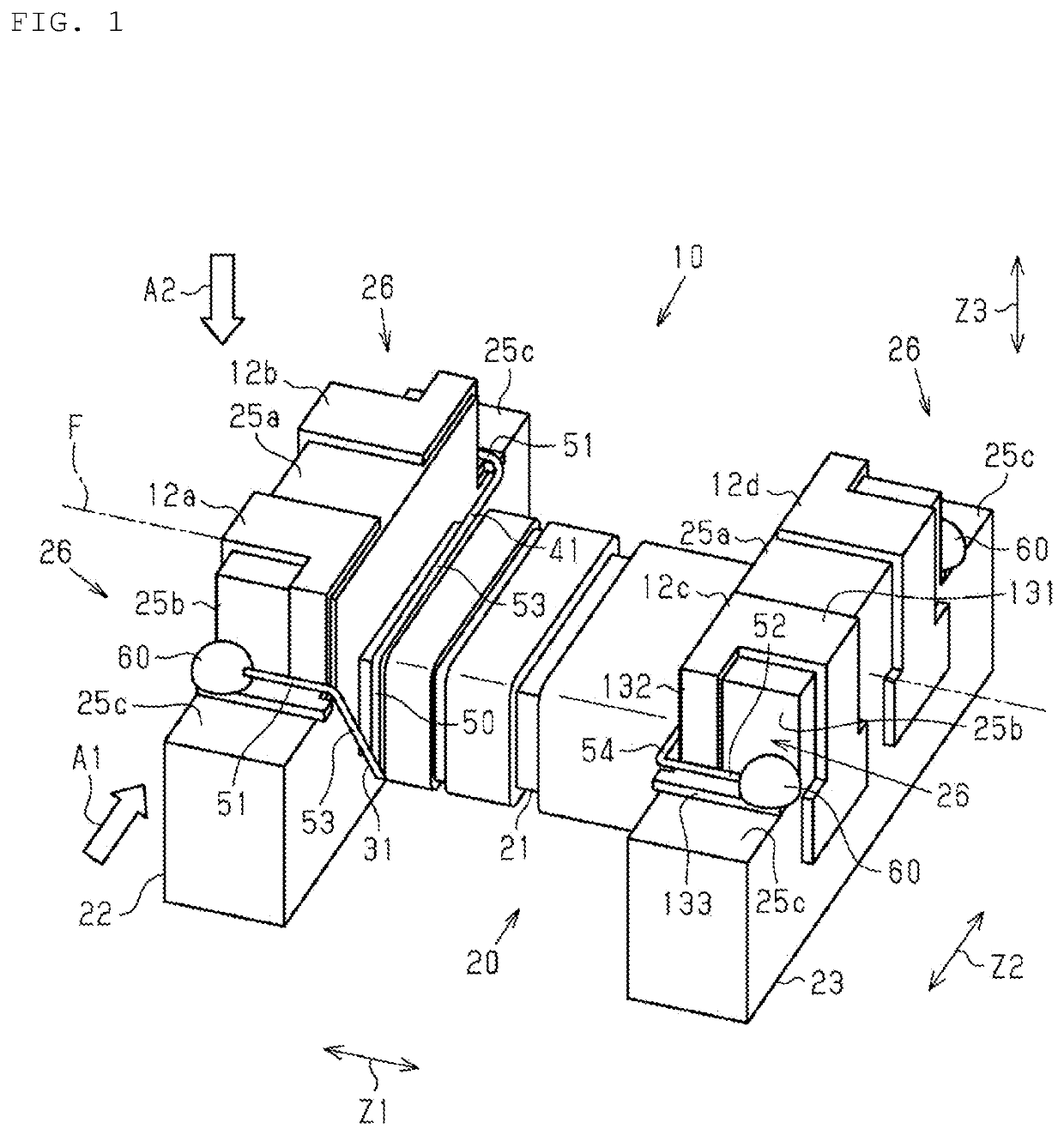
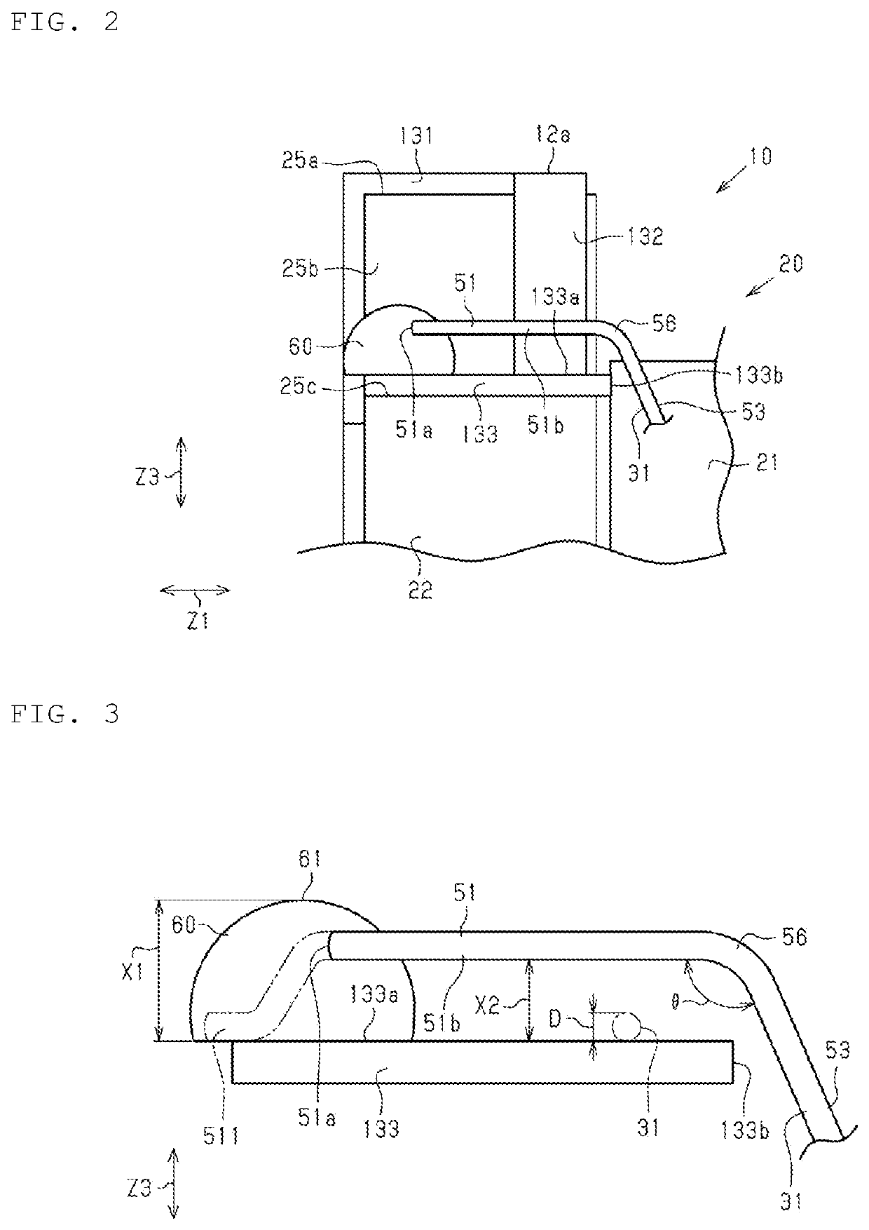
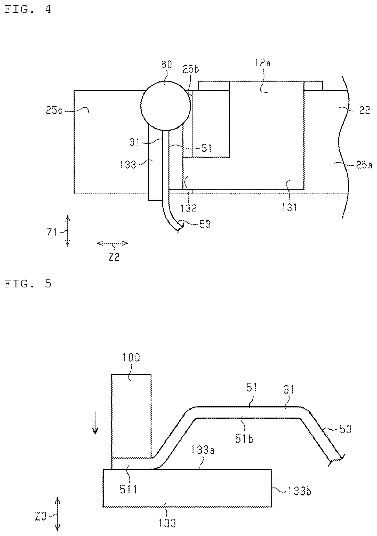
[0014]Hereinafter, an embodiment of a coil component will be described with reference to FIGS. 1 to 5. The drawings may show enlarged components to facilitate understanding. Dimensional ratios of the components may be different from those actual or those in another drawing. Although hatching is applied in a sectional view, hatching of some components may be omitted to facilitate understanding.

[0015]As illustrated in FIG. 1, a coil component 10 includes a core 20 and a plurality of wires 31 and 41 wound around the core 20. The coil component 10 is, for example, a common mode choke coil.

[0016]The core 20 contains, for example, an electrically insulating material. Specifically, the core 20 contains a non-magnetic material such as alumina or a resin, and a magnetic material such as ferrite or a magnetic powder-containing resin. The core 20 is preferably constituted by a sintered body such as alumina or ferrite.

[0017]The core 20 includes a winding core 21, a first flange 22 connected to ...


PUM


Abstract

Heat is less likely to transfer from a terminal electrode to a wire. A coil component includes a core, a first terminal electrode provided on a first flange of the core, a winding portion wound around a winding core of the core, and a first wire having a first end. The first end of the first wire is electrically connected to the first terminal electrode. A part of the first end is spaced apart from the first terminal electrode.

Description

CROSS-REFERENCE TO RELATED APPLICATION[0001]This application claims benefit of priority to Japanese Patent Application No. 2020-188962, filed Nov. 12, 2020, the entire content of which is incorporated herein by reference.BACKGROUNDTechnical Field[0002]The present disclosure relates to a coil component in which a wire is wound around a winding core of a core.Background Art[0003]Japanese Patent Application Laid-Open No. 2018-148078 discloses an example of a coil component in which a wire is wound around a winding core of a core. In this coil component, a terminal electrode is provided on a flange of the core, and an end of the wire is electrically connected to the terminal electrode.[0004]An example of a method of electrically connecting the end of the wire to the terminal electrode will be described. For example, the end of the wire is temporarily fixed to the terminal electrode by thermal pressure bonding. By melting a metal constituting the terminal electrode in this state, a molte...

Claims


Application Information

Patent Timeline
IPC IPC(8): H01F27/28
CPCH01F27/2828H01F27/2885H01F27/29H01F27/292H01F5/04H01F17/045H01F2017/0093
Inventor NAKAMOTO, SHINGOTAKEZAWA, KAORIYAMAMOTO, SHIGETO
Owner MURATA MFG CO LTD
Learn More