
Dental Treatment Apparatus

a technology for treating instruments and teeth, applied in the field of dental treatment equipment, can solve the problems of root canal complex shape, inflammation, and inability to widen the root canal, and achieve the effects of reducing treatment efficiency, reducing pain, and reducing treatment efficiency

Pending Publication Date: 2022-05-26
MORITA MFG CO LTD
View PDF0 Cites 1 Cited by
  • Summary
  • Abstract
  • Description
  • Claims
  • Application Information

AI Technical Summary

Benefits of technology

The patent is about a dental treatment machine that can use a high-frequency current to treat a root canal. The goal is to make the treatment more efficient without reducing the effectiveness of the treatment.

Problems solved by technology

The root canal, however, has a complex shape, and the shape differs from tooth type to tooth type and from person to person.
It is therefore difficult for the root canal treatment to widen some portion of the root canal even with a reamer and a file, which may cause an inflammation factor to remain such that the root canal cannot be widened and that inflammation occurs after the treatment.
A part subjected to the root canal treatment includes hard tissue such as a tooth and soft tissue such as granulation, and even when energization with a high-frequency current having the same current value is performed, pain may be caused in soft tissue where nerves exist.
For the dental treatment apparatus according to WO 2008 / 114244 A, however, only a configuration where electric pulses are automatically transmitted to the root canal via the electrode when the electrode reaches a predetermined position is disclosed, and thus, pain may be caused by energization in a manner that depends on the position of the electrode in the root canal.
Further, it is possible to apply anesthesia in order to reduce the pain caused by the energization, but, when anesthesia is applied in dental treatment, it will take about 10 minutes to 15 minutes until the effect of the anesthesia is exerted, which reduces treatment efficiency.
Furthermore, neither energization with the optimum current value nor a change in the current with which energization is performed is made in accordance with the position of the electrode in the root canal, and thus, there is a possibility of destroying important tissue at the root apex.

Method used


Image

  • Dental Treatment Apparatus
  • Dental Treatment Apparatus
  • Dental Treatment Apparatus

Examples


first embodiment

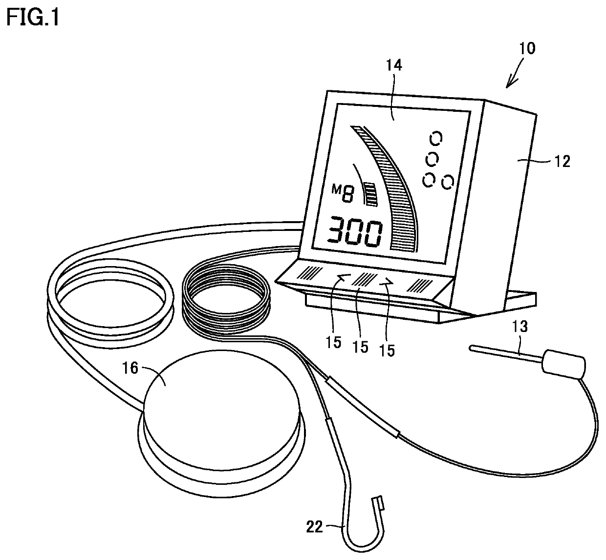
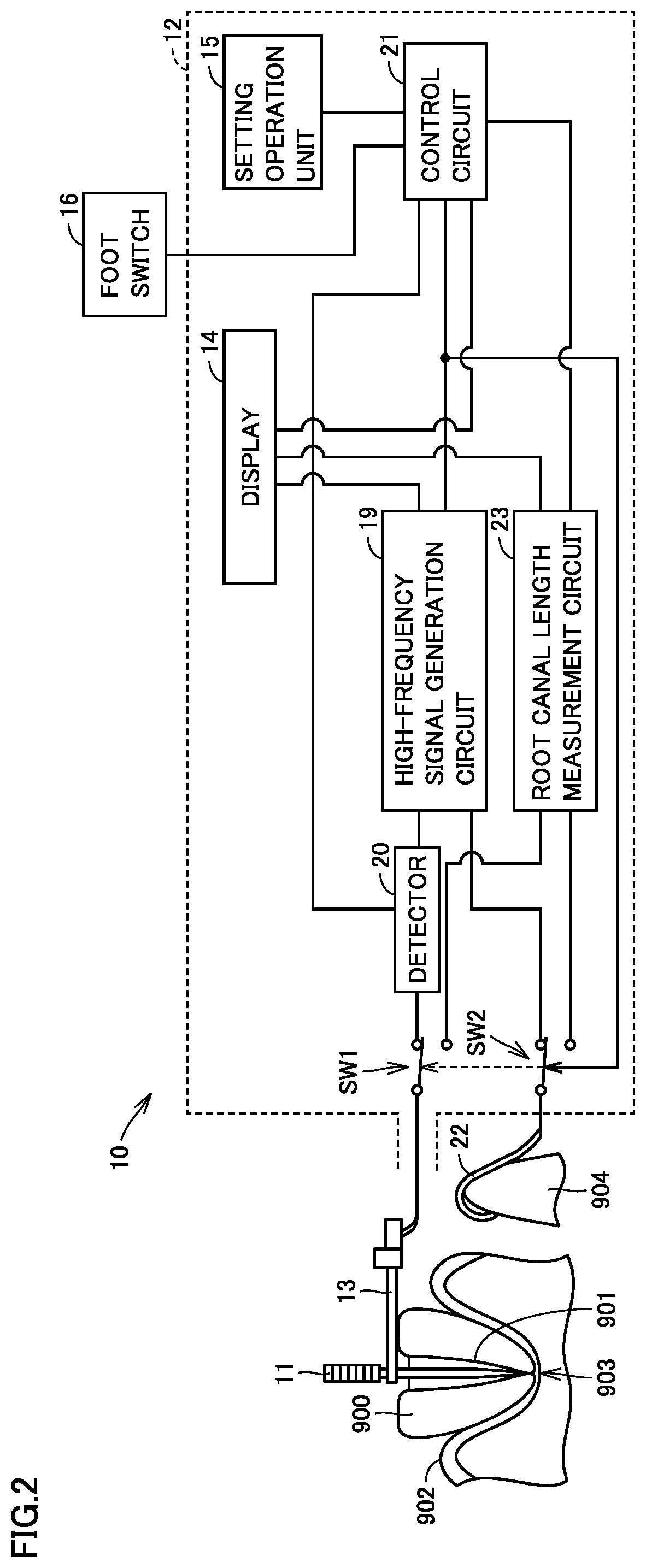
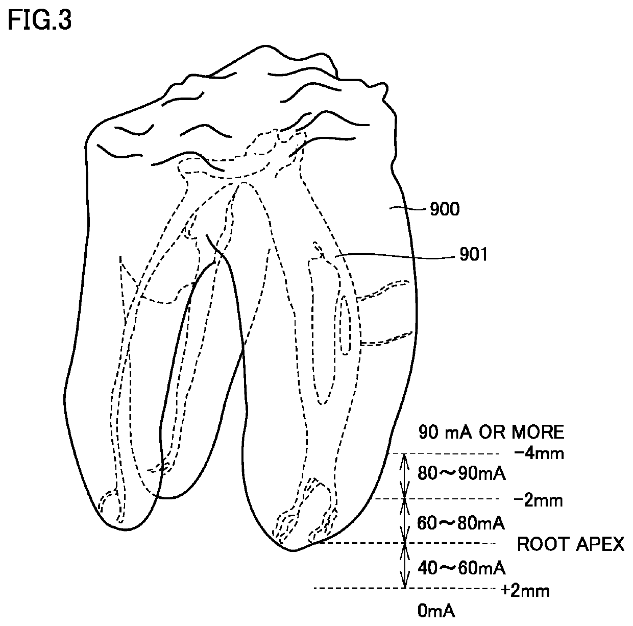
[0023]FIG. 1 is an external view of a dental treatment apparatus according to a first embodiment. FIG. 2 is a block diagram of a configuration of the dental treatment apparatus according to the first embodiment. FIG. 3 is a diagram for schematically describing a root canal of a tooth. Root canal treatment of cutting and widening a root canal of a tooth is very difficult treatment because a degree to which a root canal is curved or a degree to which a root canal is calcified and blocked, and the like are different among individuals. A tooth 900 shown in FIG. 3 is a molar tooth, and each tooth includes a plurality of root canals 901. It is difficult to perform treatment on all such complex-shaped root canals. In particular, when there is a portion where it is difficult to cut and widen a root canal using cutting tools such as a reamer and a file, the root canal in the portion cannot be cut and widened, and dental pulp or an inflammation factor remains in the root canal, inflammation m...

second embodiment

[0050]A description has been given of dental treatment apparatus 10 according to the first embodiment that energizes file 11 with the high-frequency current having the preset current value in the sterilization mode based on the information on the position of the distal end of file 11 measured in the root canal length measurement mode. As for a second embodiment, a description will be given in detail of how to control the current value of the high-frequency current with which file 11 is energized in the sterilization mode. Note that, according to the second embodiment, the same components as the components of dental treatment apparatus 10 described according to the first embodiment are denoted by the same reference numerals, and no detailed description of such components will be given below. Further, the contents of the first embodiment described above can be combined with contents of the second embodiment to the extent consistent with the second embodiment.

[0051]A description will b...

third embodiment

[0075]A description has been given of dental treatment apparatus 10 according to the first embodiment that energizes file 11 with the high-frequency current having the current value preset based on the information on the position of the distal end of file 11 measured in the root canal length measurement mode. As for a dental treatment apparatus according to a third embodiment, a description will be given of a configuration where an energization period where the file is energized with the high-frequency current is controlled based on not only the information on the position of the distal end of file 11 measured in the root canal length measurement mode but also information on the position of the distal end of file 11 measured during the pause period. Note that, according to the third embodiment, the same components as the components of dental treatment apparatus 10 described according to the first embodiment are denoted by the same reference numerals, and no detailed description of s...


PUM


Abstract

A dental treatment apparatus includes a holder, a power supply, root canal length measurement circuitry, and control circuitry. The holder holds an electrode placed in a root canal. The power supply energizes file with a high-frequency current. The root canal length measurement circuitry electrically measures a position of a distal end of electrode in the root canal. The control circuitry causes, in accordance with information on the position of the distal end of the electrode measured by root canal length measurement circuitry, the power supply to control a current value of the high-frequency current which energizes the electrode.

Description

CROSS-REFERENCE TO RELATED APPLICATIONS[0001]This application claims priority under 35 U.S.C. § 119 from Japanese Patent Application No. 2020-195975, filed Nov. 26, 2020. The entire content of the above application is incorporated herein by reference.BACKGROUND OF THE INVENTIONField[0002]The present disclosure relates to a dental treatment apparatus that energizes a dental treatment site with a high-frequency current.Description of the Background Art[0003]In the dental field, root canal treatment for teeth may be performed to remove dental pulp or to mitigate inflammation at a root apex. In such a root canal treatment, a root canal is cut and widened with a reamer and a file, contaminated tissue or contaminants in the root canal are removed, and then the root canal is filled with a medicament.[0004]The root canal, however, has a complex shape, and the shape differs from tooth type to tooth type and from person to person. It is therefore difficult for the root canal treatment to wide...

Claims


Application Information

Patent Timeline
IPC IPC(8): A61C19/04A61C5/44A61B18/12A61B18/14
CPCA61C19/042A61C5/44A61B2018/00642A61B18/1233A61B18/14A61C19/041A61C5/40A61C19/06A61C19/04A61N1/3605A61N1/326A61C5/42A61N1/06A61B2018/00595A61B2018/00702A61B2018/0072A61B2018/00732A61B2018/00738A61B2018/00779
Inventor UEDA, TOMOAKIADACHI, KOICHIROMATOBA, KAZUNARI
Owner MORITA MFG CO LTD
Learn More