Supercharge Your Innovation With Domain-Expert AI Agents!

Phase frequency response measurement method

a phase frequency response and measurement method technology, applied in the direction of instruments, code conversion, spectral/fourier analysis, etc., can solve the problems of inapplicability to analog to digital converters (adcs), limitations of conventional methods of phase frequency response measurement, and inability to use vna-based phase frequency response measurement for frequency converters

Active Publication Date: 2022-06-02
GUZIK TECHN ENTERPRISES
View PDF0 Cites 0 Cited by
  • Summary
  • Abstract
  • Description
  • Claims
  • Application Information

AI Technical Summary

Benefits of technology

The patent describes a method for reducing errors in calculating the phase response of a device, by using a specialized digitizer and comparing calculated and actual results. This method can improve the accuracy of high-speed measurements.

Problems solved by technology

The conventional methods of phase frequency response measurements, for example, based on the employment of Vector Network Analyzers (VNAs) have certain limitations which prevent their use with signal conversion devices.
As a consequence, these methods are not applicable to such devices as analog to digital converters (ADCs), where the input signal is analog and the output signal is digital.
For these reasons, VNA-based phase frequency response measurement cannot be used for frequency converters.
However, application of this method presents certain difficulties.
However, such substitutions cause changes in frequency responses of the DUT.
Construction a generator of test signals occupying a wide frequency range, with a levels varying in a large dynamic range, may present a considerable technical problem.
Also, measurement of phase frequency response is time consuming, and, therefore, using the method of the '467 patent for multiple settings of input attenuator, takes a long time and may be not practical.
This fact considerably restricts the field of application of the described method.

Method used


Image

  • Phase frequency response measurement method
  • Phase frequency response measurement method
  • Phase frequency response measurement method

Examples


Embodiment Construction

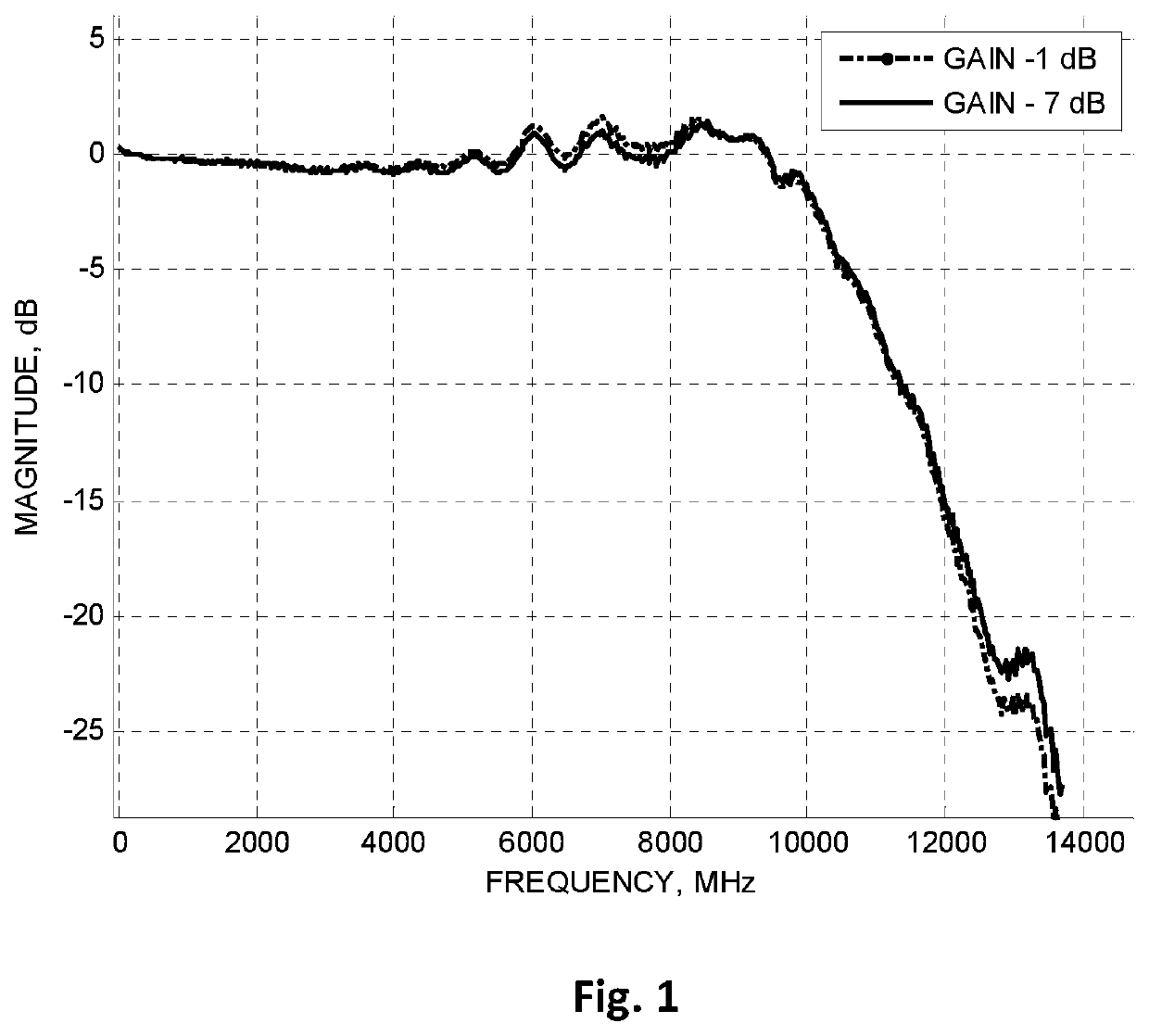
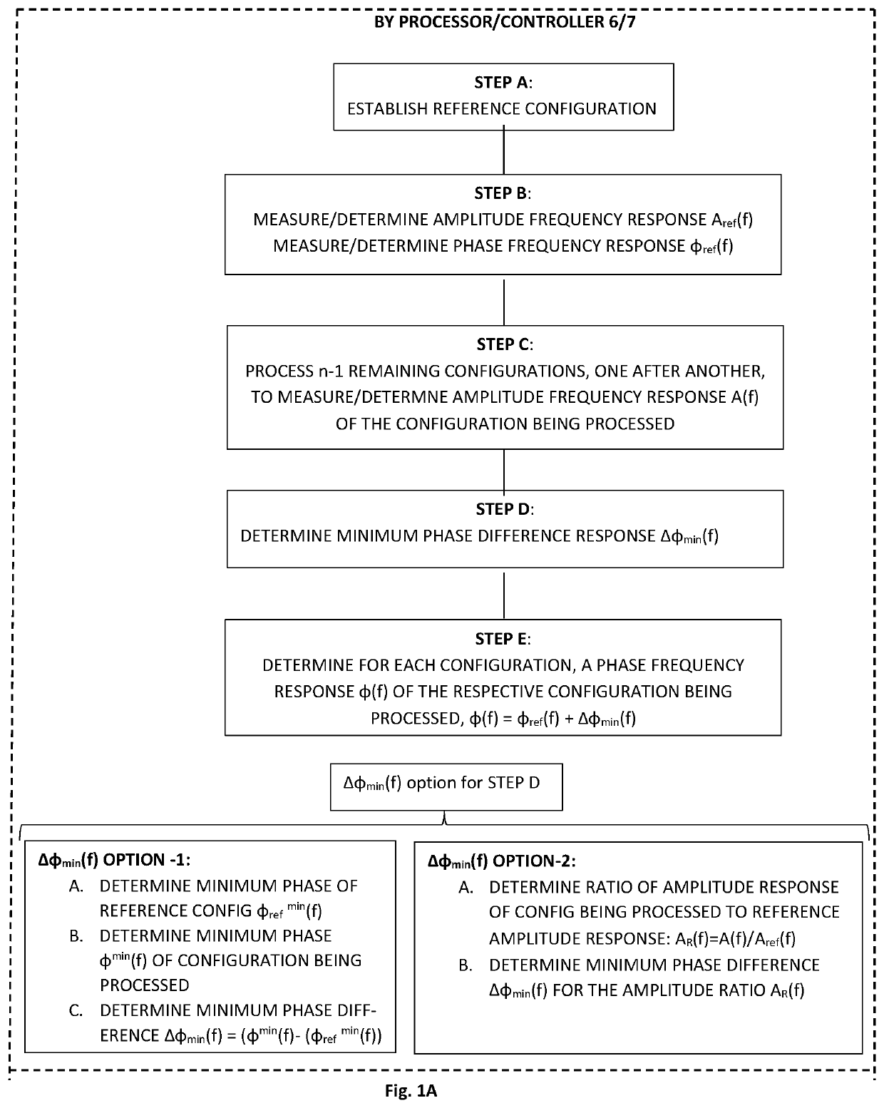
[0015]According to the present disclosure, one configuration of a DUT is chosen as a reference configuration. Preferably, a reference configuration with a level of input signal which is close to an output level of the measuring device used to determine the phase frequency response. Such a choice makes it possible to measure for the reference configuration, not only an amplitude frequency response Af(f), but a phase frequency response ϕref(f) as well.

[0016]After the amplitude frequency response Aref(f), and the phase frequency response ϕref (f) of the reference configuration have been measured, the remaining DUT configurations are processed one after another. For each configuration to be processed, the amplitude frequency response A(f) is measured. The measured amplitude frequency response A(f) together with the frequency responses Aref(f), and ϕref (f) of the reference configuration, are used as initial data for calculation of the phase frequency response ϕ(f) of the configuration ...


PUM


Abstract

A measurement of phase frequency response of a device under test (DUT), wherein the DUT is characterized by a set of switchable configurations, comprises choosing the steps of a particular configuration of the DUT having nominal parameters as a reference configuration, measuring an amplitude frequency response Aref (f) and a phase frequency response ϕref(f) of the reference configuration, processing all configurations of the DUT which are different from the reference configuration, one after another, by measuring an amplitude response A(f) of the configuration being processed, calculating a minimum phase difference response Δϕmin (f); and calculating for each configuration, a phase frequency response ϕ(f) of the respective configuration which is being processed, in accordance with ϕ(f) =ϕref(f)+Δϕmin(f).

Description

FIELD OF THE INVENTION[0001]The technology relates to measurement of phase frequency response of a device under test (DUT), including, but not limited to signal conversion devices, such as high speed analog to digital converters, analog and digital up-converters, down-converters and others.BACKGROUND OF THE INVENTION[0002]Signal conversion devices are characterized by a frequency response, consisting of amplitude and phase terms. Correction (equalization) of the frequency response is essential for a high quality converter and requires precise measurement of device properties and the phase response dependence on frequency in particular.[0003]The conventional methods of phase frequency response measurements, for example, based on the employment of Vector Network Analyzers (VNAs) have certain limitations which prevent their use with signal conversion devices. First, they require a DUT to have input and output ports which are both of the analog type. As a consequence, these methods are ...

Claims


Application Information

Patent Timeline
Patent Type & Authority Applications(United States)
IPC IPC(8): G01R31/28H03M1/10
CPCG01R31/2837H03M1/1095G01R23/18
Inventor SEREBRYANSKIY, VALERIYVOLFBEIN, SEMEN P.
Owner GUZIK TECHN ENTERPRISES
Features
  • R&D
  • Intellectual Property
  • Life Sciences
  • Materials
  • Tech Scout
  • Unparalleled Data Quality
  • Higher Quality Content
  • 60% Fewer Hallucinations
Learn More