Cooler and semiconductor apparatus

Pending Publication Date: 2022-06-02
FUJI ELECTRIC CO LTD
View PDF0 Cites 0 Cited by
  • Summary
  • Abstract
  • Description
  • Claims
  • Application Information

AI Technical Summary

Benefits of technology

[0010]According to the present invention, local corrosion a

Problems solved by technology

Because a coolant flows, corrosion may occur on an inner surface of the cooler.
The cooler ha

Method used


Image

  • Cooler and semiconductor apparatus
  • Cooler and semiconductor apparatus
  • Cooler and semiconductor apparatus

Examples


Example

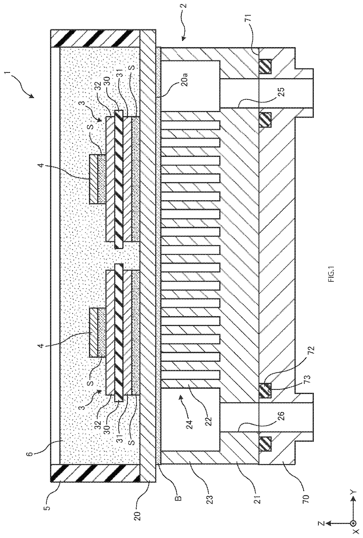
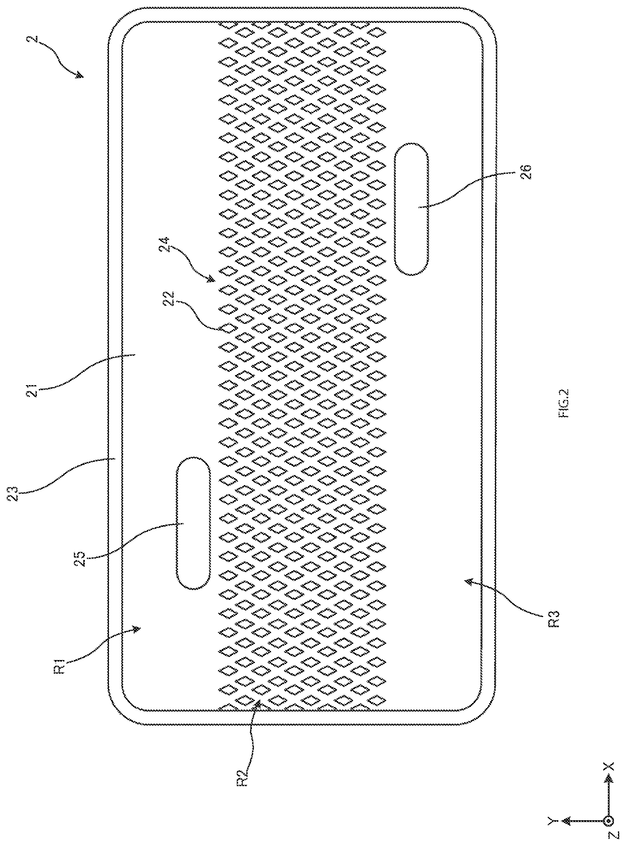
[0018]A semiconductor apparatus to which the present invention is applicable is described below. FIG. 1 is a cross-sectional view of a semiconductor apparatus according to an embodiment. FIG. 2 is a plan view of a cooler according to the embodiment from which a top plate thereof is omitted and which is viewed from its upper surface side. The semiconductor apparatus to be described later is merely an example, and changes can be made as required without limiting thereto.

[0019]In the following drawings, a longitudinal direction of the semiconductor apparatus (cooler) (or a direction in which a plurality of phases are aligned), a transverse direction of the semiconductor apparatus (cooler) and a height direction (direction of thickness of a substrate) are defined as an X direction, a Y direction and a Z direction, respectively. The shown axes of X, Y, Z are orthogonal to each other and form a right-handed system. In some cases, the X direction, the Y direction and the Z direction may be...


PUM


Abstract

A cooler includes a top plate, one surface of which serves as a heat dissipation surface, a bottom plate disposed so as to face the top plate and having a larger thickness than that of the top plate, a plurality of fins provided between the top plate and the bottom plate, and a circumferential wall part provided so as to surround the plurality of fins along outer circumferential edges of the bottom plate. The plurality of fins and the outer circumferential wall part are provided between the top plate and the bottom plate and bonded to the heat dissipation surface of the top plate. A flow path for a coolant is formed by a space enclosed by the top plate, the bottom plate, the plurality of fins, and the circumferential wall part. The top plate has an electric potential higher than that of the bottom plate.

Description

CROSS REFERENCE TO RELATED APPLICATIONS[0001]This application is based upon and claims the benefit of priority of the prior Japanese Patent Application No. 2020-199467, filed on Dec. 1, 2020, the entire contents of which are incorporated herein by reference.BACKGROUND OF THE INVENTIONField of the Invention[0002]The present invention relates to a cooler and a semiconductor apparatus.Description of the Related Art[0003]A general-purpose heat exchanger (cooler) is formed of a metallic material having good heat conductivity such as an aluminum alloy (see Japanese Patent Laid-Open No. 9-070658 and 2009-293888). For example, Japanese Patent Laid-Open No. 9-070658 discloses a method for manufacturing a so-called finned tube heat exchanger. According to Japanese Patent Laid-Open No. 9-070658, an extruded flat tube made of an aluminum alloy and fins are bonded with a brazing material. Also, according to Japanese Patent Laid-Open No. 2009-293888, a corrugated plate is placed between a pair of...

Claims


Application Information

Patent Timeline
IPC IPC(8): H01L23/473H01L23/367
CPCH01L23/473H01L23/3675H01L23/3672H01L23/3735H01L23/4334H01L23/3677H01L2224/32225H01L2924/10272H01L2924/10254H01L2924/1033H01L2924/1203H01L2924/13055H01L2924/13091H01L2224/291H01L24/29H01L24/32H01L23/24H01L23/053H01L2924/014H01L2924/00014
Inventor MATSUZAWA, KENSUKEKOYAMA, TAKAHIROGOHARA, HIROMICHI
Owner FUJI ELECTRIC CO LTD
Why Eureka
Try Eureka