Laser hot wire welding of multi-layered structures

Active Publication Date: 2019-10-24
LINCOLN GLOBAL INC
View PDF0 Cites 4 Cited by
  • Summary
  • Abstract
  • Description
  • Claims
  • Application Information

AI Technical Summary

Benefits of technology

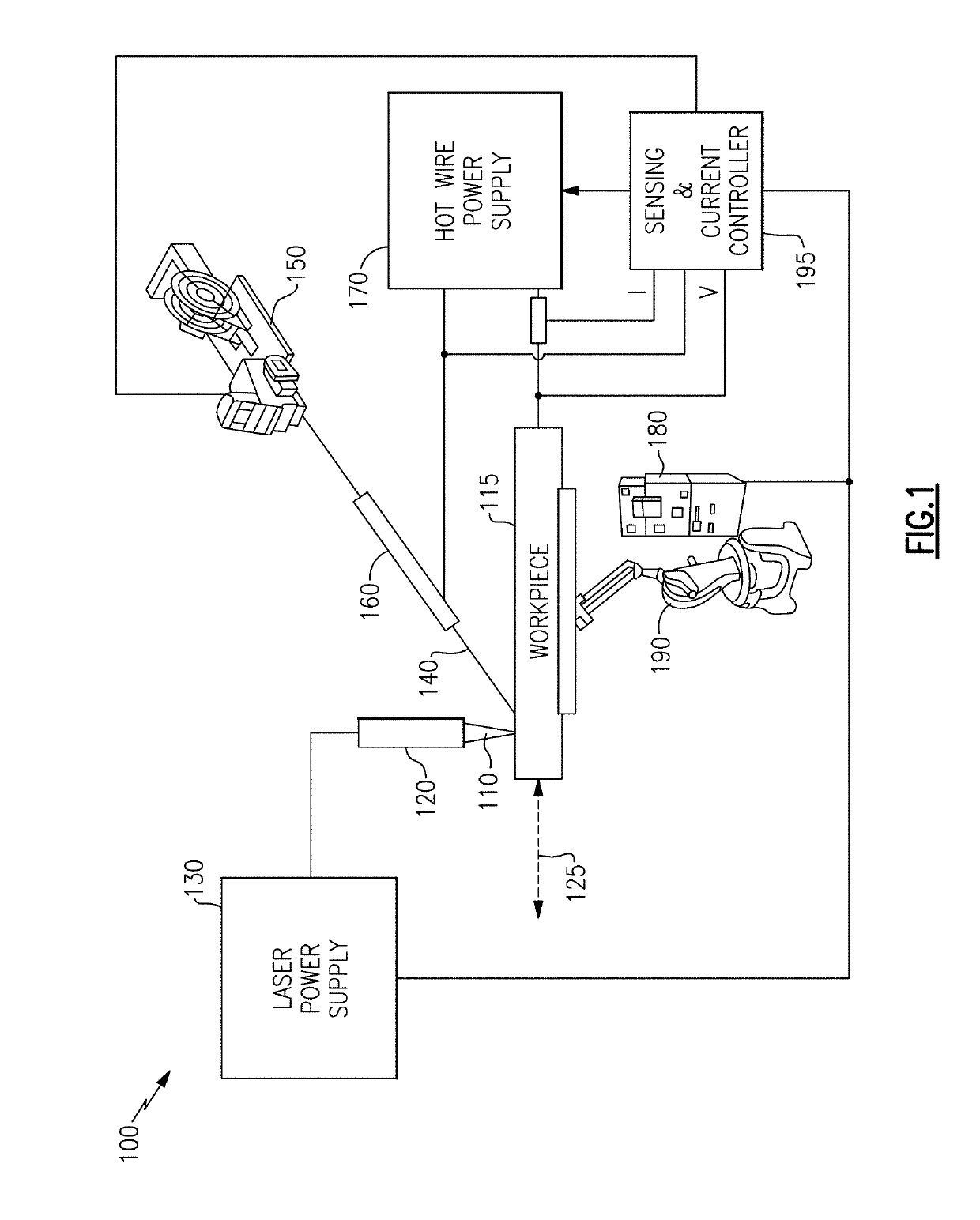
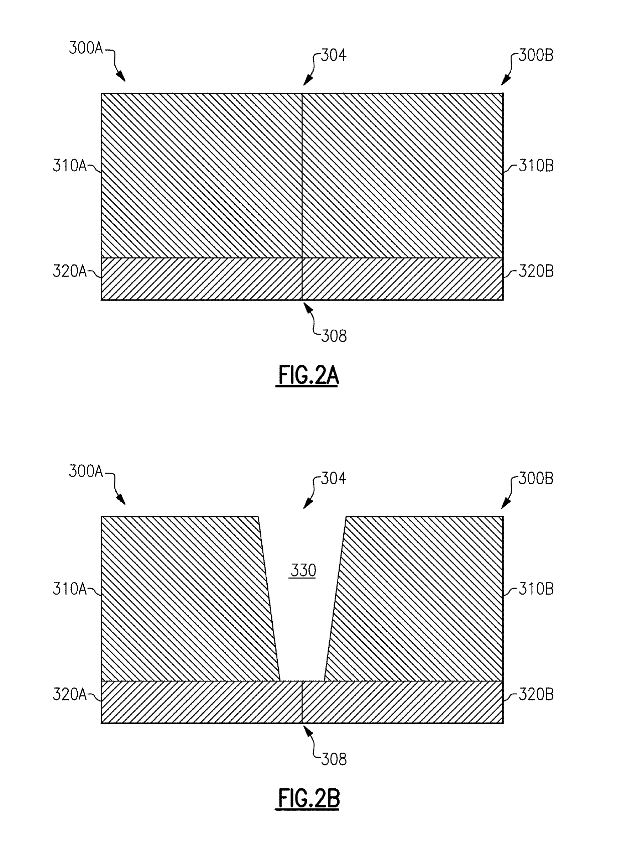
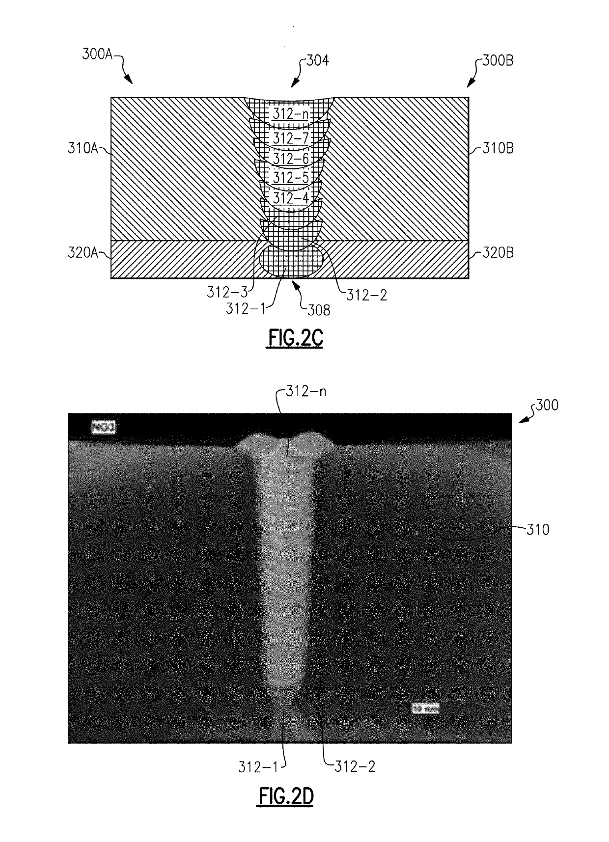
[0003]In an aspect, a method of welding multi-layered metallic workpieces comprises providing a pair of multi-layered workpieces. Each of the workpieces has having a base layer formed over a corrosion resistant layer comprising a corrosion resistant element. The method additionally comprises forming a root pass weld bead to join the corrosion resistant layers of the workpieces using a first filler wire comprising the corrosion resistant element. The method additionally comprises forming one or more weld beads to join base layers over the root pass weld bead to join the base layers of the workpieces by resistively heating a second filler wire while directing a laser beam over the root pass weld bead, such that a concentration of the corrosion resistant element in one of the one or more weld beads is less than 50% of a concentration of the corrosion-resistant element in the root pass weld bead.
[0004]In another aspect, a method of forming a weld joint comprises providing a pair of multi-layered workpieces each having an base layer and a cladding layer, the cladding layer comprising a corrosion resistant element adapted to suppress corrosion in a ferrous alloy and the base layer comprising the ferrous alloy. The method additionally comprises forming a root pass weld bead to join the cladd

Problems solved by technology

However, metal components formed of a uniform material that satisfies one performance parameter may not satisfy other performance parameters.
However, welding metal workpieces formed of multi-l

Method used


Image

  • Laser hot wire welding of multi-layered structures
  • Laser hot wire welding of multi-layered structures
  • Laser hot wire welding of multi-layered structures

Examples


Example

[0013]Some metal components such as tubes and pipes are used in environments or conditions that demand competing technical challenges. For example, some tubes and pipes may be employed in environments where superior mechanical performance as well as superior chemical performance, e.g., high corrosion resistance, are demanded. However, an alloy that satisfies one of the performance parameters may not satisfy another one of the performance parameters. Thus, for some applications, competing technical challenges may be met by metal components formed of multi-layered structures.

[0014]One such application is offshore oil and gas transport, where welded tubes and pipes are designed to withstand high pressure as well as harsh corrosive environments. The performance demands in the oil and gas industries are becoming increasingly challenging, including higher temperatures, higher pressures, higher corrosion and higher wear, at least in part due to the fact that an increasing percentage of wor...


PUM

PropertyMeasurementUnit
Fractionaaaaaaaaaa
Fractionaaaaaaaaaa
Thicknessaaaaaaaaaa

Abstract

The disclosed technology generally relates to welding, and more particularly to welding multi-layered structures. In an aspect, a method of welding multi-layered metallic workpieces comprises providing a pair of multi-layered workpieces. Each of the workpieces has a base layer and an cladding layer, where the cladding layer comprises a corrosion resistant element adapted to suppress corrosion in a ferrous alloy. The method additionally comprises forming a root pass weld bead to join cladding layers of the workpieces using a first filler wire comprising the corrosion resistant element and focusing a first laser beam on the cladding layers. The method additionally comprises forming one or more weld beads to join base layers of the workpieces by resistively heating a second filler wire and directing a second laser beam over the root pass weld bead. The method is such that a concentration of the corrosion-resistant element in the one or more weld beads is less than 50% of a concentration of the corrosion-resistant element in the root pass weld bead.

Description

BACKGROUNDField of the Invention[0001]The disclosed technology generally relates to welding, and more particularly to welding multi-layered structures.Description of the Related Art[0002]Some welded metal components such as tubes and pipes are used in environments or conditions that demand competing technical challenges. For example, some tubes and pipes may be employed in applications where superior mechanical performance as well as superior chemical performance, e.g., high corrosion resistance, are demanded. One such application is offshore oil and gas transport, where welded tubes and pipes are designed to withstand high pressure as well as harsh corrosive environments. However, metal components formed of a uniform material that satisfies one performance parameter may not satisfy other performance parameters. For some applications, metal components formed of multi-layered structures are used to meet the competing technical challenges. However, welding metal workpieces formed of m...

Claims


Application Information

Patent Timeline
IPC IPC(8): B23K26/24B23K26/323B23K35/40
CPCB23K26/323B23K35/40B23K26/24B23K1/0056B23K3/047B23K3/063B23K9/0026B23K9/0286B23K9/1093B23K9/232B23K9/235B23K26/211B23K26/282B23K2101/04B23K2101/34B23K2103/04B23K2103/166B23K2103/18
Inventor DENNEY, PAUL E.LATESSA, MICHAEL D.PETERS, STEVEN R.
Owner LINCOLN GLOBAL INC
Why Eureka
Try Eureka