
Method for operating a crane, and crane

a crane and crane technology, applied in the field of cranes, to achieve the effect of improving the operation of the cran

Active Publication Date: 2022-06-09
TADANO FAUN
View PDF8 Cites 0 Cited by
  • Summary
  • Abstract
  • Description
  • Claims
  • Application Information

AI Technical Summary

Benefits of technology

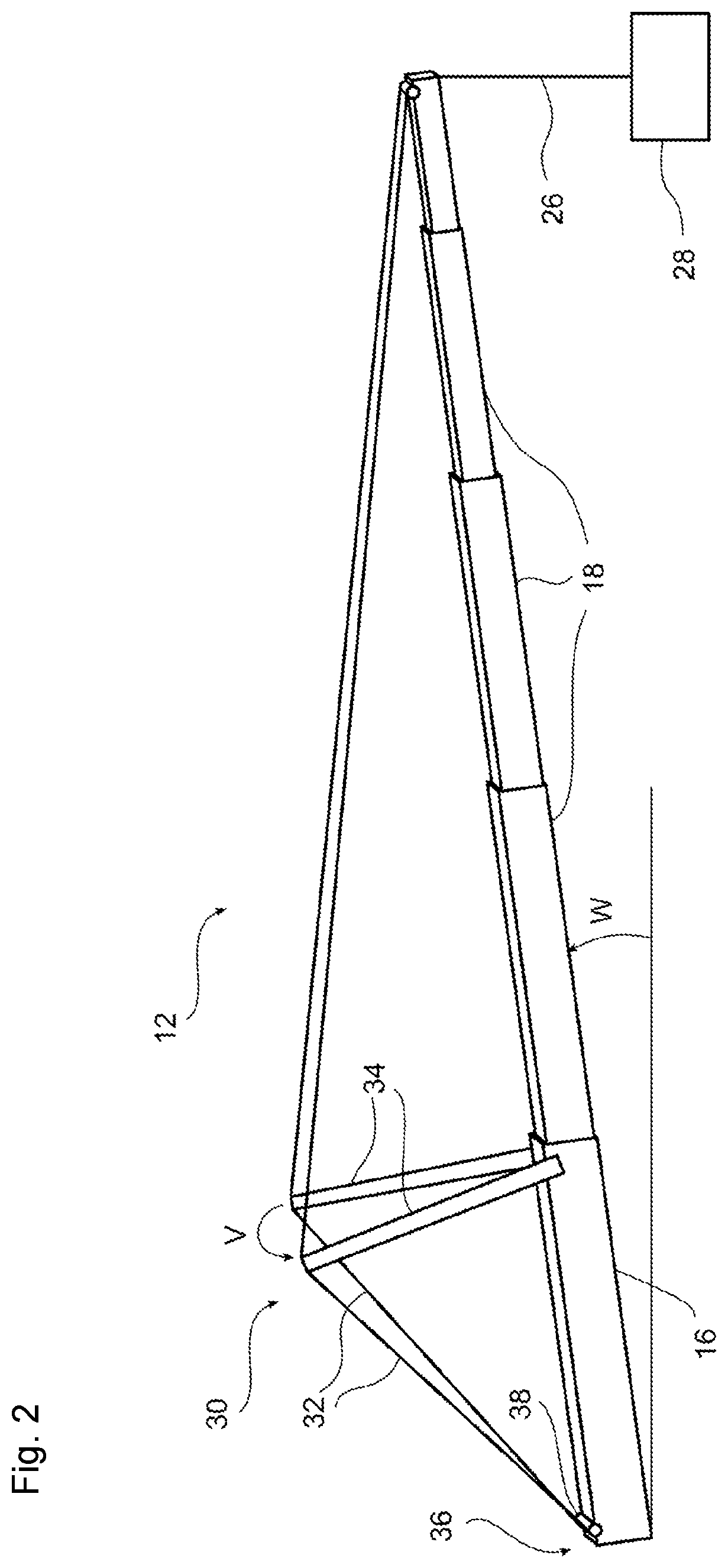
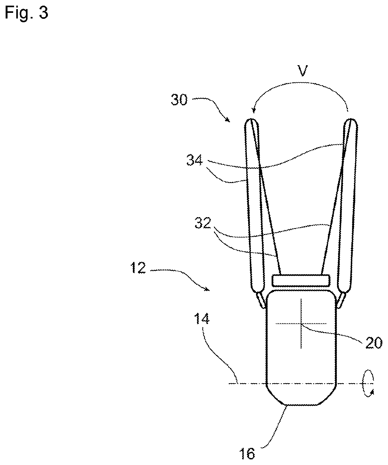
The invention provides a method for operating a crane that overcomes the disadvantages of previous methods and improves crane operation. The method involves adjusting the spread angle between tensioning posts based on the luffing angle, which is the angle at which the crane jib is positioned. By adjusting the spread angle, the stability of the crane jib can be adapted to the current load and the risk of buckling can be reduced. The method allows for a continuous adjustment of the spread angle, resulting in a higher load capacity for the crane. The angle of inclination of the luffing tip can also be considered when setting the spread angle. Overall, the method improves the stability and load capacity of the crane.

Problems solved by technology

Mobile cranes are consequently very flexible and can thus, as required, also be erected on the construction site for just a short period of time, for example in order to build a tower crane or in the case of short deployment times where it would be too expensive to build a tower crane.

Method used


Image

  • Method for operating a crane, and crane
  • Method for operating a crane, and crane
  • Method for operating a crane, and crane

Examples


Embodiment Construction

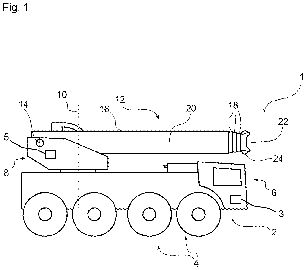
[0035]Referring now in detail to the figures of the drawings, in which mutually corresponding parts and dimensions are always provided with the same reference symbols, and first, particularly, to FIG. 1 thereof, there is seen a crane, specifically a mobile crane 1, which is diagrammatically illustrated. The crane includes an undercarriage 2 which in turn has a chassis with a plurality of axles carrying wheels 4, and a cab 6. The mobile crane 1 moreover includes a superstructure 8 which is articulated on the undercarriage 2 so that it can be slewed about a vertical axis 10. The mobile crane 1 moreover includes a crane jib 12 which forms a part of the superstructure 8 and is articulated on a mounting of the superstructure 8 so that it can be swiveled (can be “luffed”, i.e. its inclination can be adjusted) about a luffing axis 14. The crane jib 12 is telescopic and for this purpose has a base segment 16 in which a plurality of jib segments 18, each of which has a reduced cross-section,...


PUM


Abstract

A crane, in particular a mobile crane, includes a crane jib which can be moved about a substantially horizontal luffing axis, and a tensioning device for the crane jib. The tensioning device includes two pendants which run from the jib tip to the jib base of the crane jib and tensioning posts each tensioning a respective one of the pendants relative to the crane jib in a triangular configuration. In order to operate the crane, a luffing angle of the crane jib about the luffing axis is measured or recorded, and a spread angle between the tensioning posts while the crane jib is being used is modified depending on the luffing angle.

Description

CROSS-REFERENCE TO RELATED APPLICATION[0001]This application claims the priority, under 35 U.S.C. § 119, of German Patent Application DE 10 2020 215 260.8, filed Dec. 3, 2020; the prior application is herewith incorporated by reference in its entirety.FIELD AND BACKGROUND OF THE INVENTION[0002]The invention relates to a crane, in particular a mobile crane, which has a crane jib which can be moved (i.e. can be inclined or luffed) about a luffing axis which is usually oriented horizontally. The invention moreover relates to a method for operating such a crane.[0003]As is known, cranes serve to handle loads on construction sites, usually in the form of (revolving) tower cranes or also mobile cranes. The former are erected on a stationary erection site and usually remain in this place during the construction work. In contrast, mobile cranes usually have a self-propelled frame (usually referred to as the “undercarriage”) on which a usually telescopic crane jib or a lattice boom jib is di...

Claims


Application Information

Patent Timeline
IPC IPC(8): B66C23/82B66C23/70B66C13/18
CPCB66C23/828B66D2700/01B66C13/18B66C23/701B66C23/826B66C23/36
Inventor KEILHAUER, DAVIDEBINGER, TOBIASSKUDLAREK, DENNIS
Owner TADANO FAUN
Learn More