Lean burn combustor

a combustible and burnt technology, applied in the direction of burners, combustion types, combustion processes, etc., can solve the problems of passenger discomfort, engine fatigue failure, etc., and achieve the effect of reducing nox and smoke, reducing fatigue failure, and maximizing combustion efficiency

Active Publication Date: 2022-06-09
ROLLS ROYCE PLC +1
View PDF0 Cites 0 Cited by
  • Summary
  • Abstract
  • Description
  • Claims
  • Application Information

AI Technical Summary

Benefits of technology

[0011]The present inventors have found a unique non-dimensional parameter combination for the combustor chamber that allows combustor aerodynamics developing to optimise combustion efficiency and minimise NOX and Smoke. The lean burn combustor according to the disclosure allows for a so-called S-shaped recirculation zone to form in the primary combustion zone of the combustor chamber, which allows the pilot fuel nozzle to support the main fuel nozzle combustion. In particular, the present inventors have found that a combustor chamber according to the disclosure allows the burning mixture of pilot fuel and air coming from the pilot fuel injector to form an S-shaped flow recirculation. In detail, the burning mixture of pilot fuel and air coming from the pilot fuel injector may arrive at a stagnation point in the primary combustion zone, where the pilot fuel and air mixture local velocity is zero, go backwards towards the lean burn fuel injectors, and be diverted (due to low static pressure in the main flow stream) towards the radially inner and radially outer annular walls of the combustor chamber to join the burning mixture of main fuel and air coming from the main fuel injector and support the combustion thereof. In other words, the burning mixture of pilot fuel and air coming from the pilot fuel injector may flow along an S-shaped trajectory.
[0012]The skilled person would appreciate that when designing a combustor chamber for a lean burn combustor, aerodynamics study have to be carried out for any combustor chamber size in order to optimise the fuel and air mixture aerodynamics and combustion. The present inventors have surprisingly found that a lean burn combustor according to the disclosure can be scaled up and down without affecting the combustion efficiency. In other words, as the ratio D / d is non-dimensional, for a wide size range of the combustor chamber of the lean burn combustor according to the disclosure, the S-shaped recirculation zone can be effectively and efficiently formed within the primary combustion zone.
[0027]The inventors of the present disclosure have also found that other non-dimensional parameters may be advantageous when designing a combustor chamber for a lean burn combustor with improved combustion efficiency.

Problems solved by technology

On the other hand, keeping the combustion temperature relatively low could lead to incomplete or weak combustion, which in turn may lead to producing other pollutants, such as carbon monoxide (CO) and unburned hydrocarbons (UHC), and / or flame instability and rumble, which in turn may cause fatigue failure of components in the engine and / or passenger discomfort, depending on the frequency of the rumbling.
Gas turbine engines for industrial and marine applications face similar challenges as gas turbine engines for aircraft applications.

Method used


Image

  • Lean burn combustor
  • Lean burn combustor
  • Lean burn combustor

Examples


Embodiment Construction

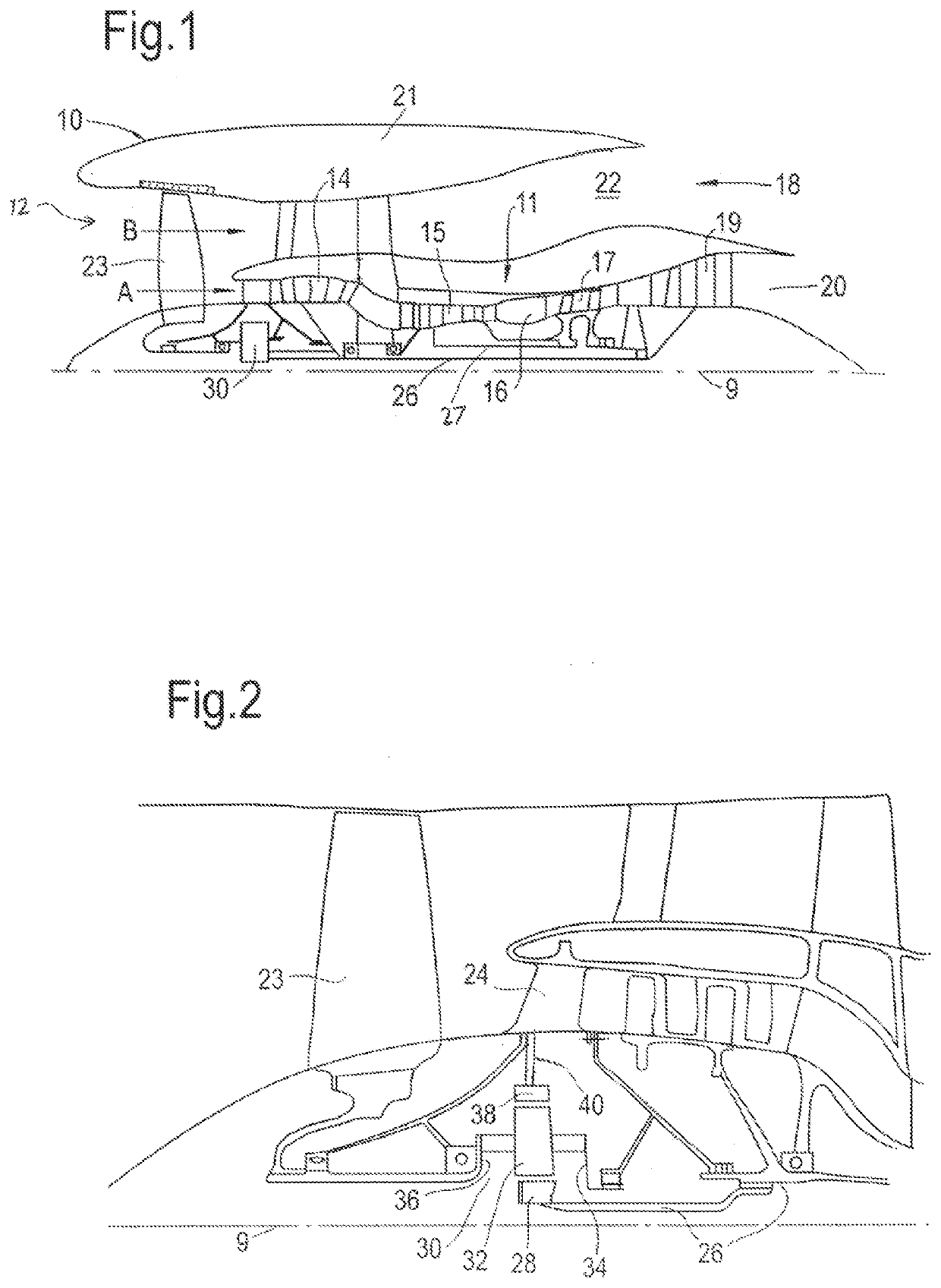
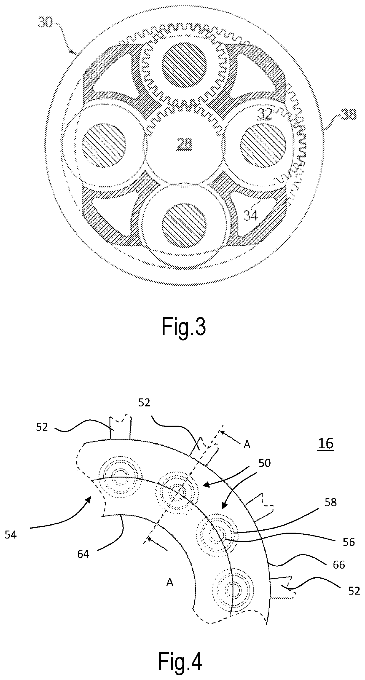
[0071]With reference to FIG. 1, a gas turbine engine, generally indicated at 10, has an engine principal rotational axis 9. The engine 10 comprises an air intake 12 and a propulsive fan with a plurality of fan blades 23 that generates two airflows: a core airflow A and a bypass airflow B. The gas turbine engine 10 comprises a core 11 that receives the core airflow A. The engine core 11 comprises, in axial flow series, a low pressure compressor 14, a high-pressure compressor 15, combustion equipment comprising a lean burn combustor 16, a high-pressure turbine 17, a low pressure turbine 19 and a core exhaust nozzle 20. A nacelle 21 generally surrounds the gas turbine engine 10 and defines a bypass duct 22 and a bypass exhaust nozzle 18. The bypass airflow B flows through the bypass duct 22. The fan is attached to and driven by the low pressure turbine 19 via a shaft 26 and an epicyclic gearbox 30.

[0072]In use, the core airflow A is accelerated and compressed by the low pressure compre...


PUM


Abstract

A lean burn combustor includes a plurality of lean burn fuel injectors, each including a fuel feed arm and a lean burn fuel injector head with a lean burn fuel injector head tip, wherein the tip has a lean burn fuel injector head tip diameter, the lean burn fuel injector head including a pilot fuel injector and a main fuel injector, the main fuel injector being arranged coaxially and radially outwards of the pilot fuel injector; and a combustor chamber extending along an axial direction and including a radially inner annular wall, a radially outer annular wall, and a meter panel defining the size and shape of the combustor chamber, which includes a primary combustion zone with a primary combustion zone depth and a secondary combustion zone. A ratio of the primary combustion zone depth to the lean burn fuel injector head tip diameter is less than 2.4.

Description

CROSS-REFERENCE TO RELATED APPLICATIONS[0001]This specification is based upon and claims the benefit of priority from UK Patent Application Number 2019219.1 filed on Dec. 7, 2020, the entire contents of which are incorporated herein by reference.BACKGROUNDField of the Disclosure[0002]The present disclosure relates to combustion equipment, and in particular to lean burn combustors for gas turbine engines for aircraft, industrial, and marine applications.2. DESCRIPTION OF THE RELATED ART[0003]A gas turbine engine for aircraft applications typically comprises, in axial flow arrangement, a fan, one or more compressors, a combustion system and one or more turbines. The combustion system typically comprises a plurality of fuel injectors having fuel spray nozzles which combine fuel and air flows and generate sprays of atomised liquid fuel into a combustion chamber. The mixture of air and atomised liquid fuel is then combusted in the combustion chamber and the resultant hot combustion produ...

Claims


Application Information

Patent Timeline
Patent Type & Authority Applications(United States)
IPC IPC(8): F23R3/34F23R3/46F23D14/58F23D14/70F02K3/06
CPCF23R3/343F23R3/46F23D14/58F23D14/70F23D2206/10F05D2220/36F05D2240/35F05D2240/30F02K3/06F23R3/38F23R3/58F23R3/50F23R3/16F23R3/283
Inventor TENTORIO, LUCABAGCHI, IMON-KALYAN
Owner ROLLS ROYCE PLC
Why Eureka
Try Eureka