Optical transceiver module

a technology of optical transceivers and optical transceivers, applied in the field of optical transceivers, can solve the problems of difficult removal of the engagement portion, and achieve the effect of reducing electromagnetic interference and effectively reducing electromagnetic interferen

Pending Publication Date: 2022-06-09
DELTA ELECTRONICS INC
View PDF9 Cites 0 Cited by
  • Summary
  • Abstract
  • Description
  • Claims
  • Application Information

AI Technical Summary

Benefits of technology

The present invention provides an optical transceiver module with a fixed engagement portion between the sidewalls, reducing the chances of the engagement portion coming off easily. Additionally, the cover structure reduces gaps between the housing and the engagement component, reducing assembly shake and electromagnetic interference. Furthermore, the engagement component is covered inside the housing, only making direct contact with the system connector's spring plates, further reducing electromagnetic interference.

Problems solved by technology

By extending the first engagement portion between the first sidewall and the second sidewall, the plug stroke of the engagement portion can be fixed, so that the engagement portion is not easy to come off.

Method used


Image

  • Optical transceiver module
  • Optical transceiver module
  • Optical transceiver module

Examples


Embodiment Construction

[0025]The present invention will now be described more specifically with reference to the following embodiments. It is to be noted that the following descriptions of preferred embodiments of this invention are presented herein for purpose of illustration and description only. It is not intended to be exhaustive or to be limited to the precise form disclosed.

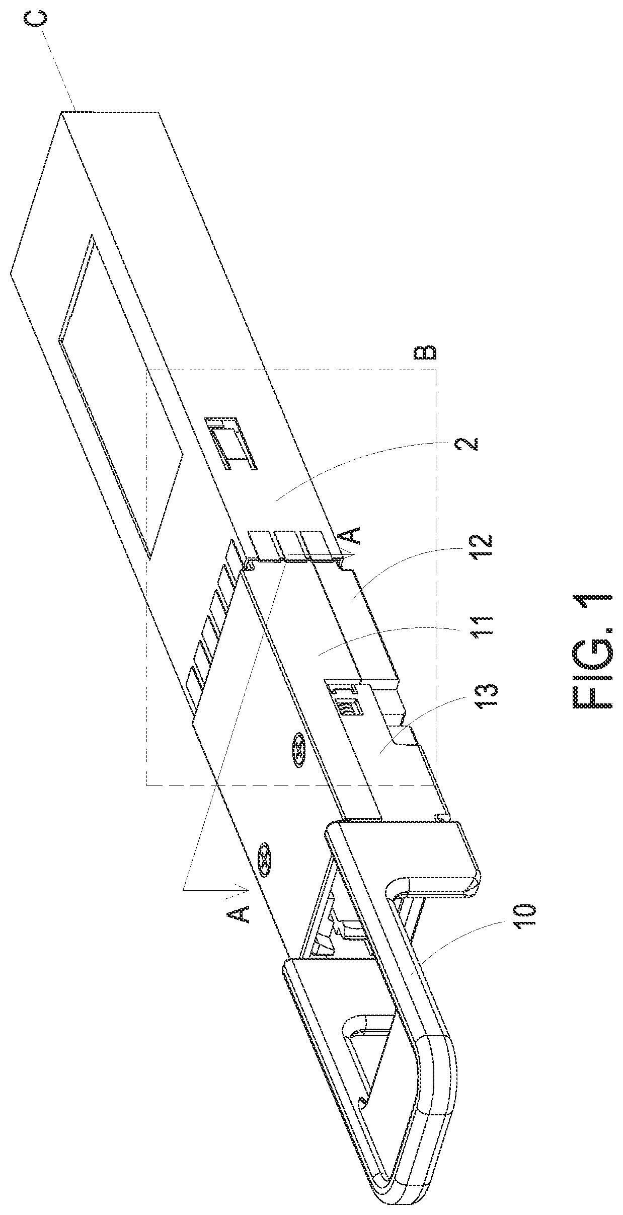
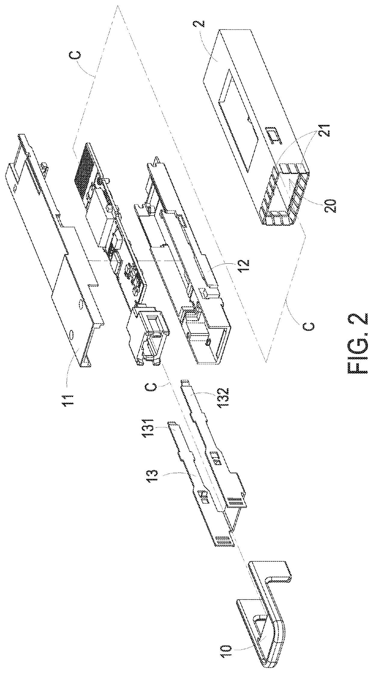
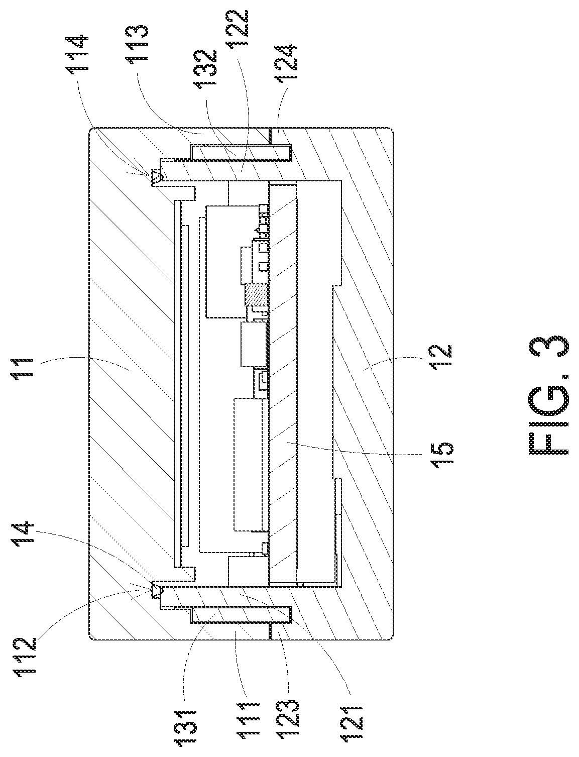
[0026]Please refer to FIG. 1, FIG. 2, and FIG. 3. FIG. 1 schematically illustrates the structural view of an optical transceiver module installed to a system connector according to an embodiment of the present invention. FIG. 2 schematically illustrates the exploded view of an optical transceiver module installed to a system connector according to an embodiment of the present invention. FIG. 3 schematically illustrates the sectional view of the line A-A shown in FIG. 1 showing an optical transceiver module which is not installed to a system connector. As shown in FIG. 1, FIG. 2, and FIG. 3, an optical transceiver module according...


PUM


Abstract

An optical transceiver module includes a first housing, a second housing, an engagement component, a conductive body, and a circuit board. The first housing has a first sidewall and a first groove. The first groove is closer to a central line of a major axis of the first housing than the first sidewall. The second housing is assembled with the first housing. The second housing has a second sidewall. The second sidewall is extended into the first groove. The engagement component has a first engagement portion. The first engagement portion is extended between the first sidewall and the second sidewall. The conductive body is disposed between the first groove and the second sidewall. The circuit board is disposed between the first housing and the second housing to perform photoelectric conversion. Therefore, the stroke of the engagement component can be fixed, and the electromagnetic interference can be reduced.

Description

FIELD OF THE INVENTION[0001]The present invention relates to an optical transceiver module, and more particularly to an optical transceiver module reducing electromagnetic interferences.BACKGROUND OF THE INVENTION[0002]Optical transceiver modules are widely applied in information and communication fields. The common ones include quad small form-factor pluggable (QSFP) transceiver and quad small form-factor pluggable double density (QSFP-DD) transceiver. With growing of the transmission requirements of optical transceiver modules, the requirements of reducing the electromagnetic interferences are also increased.[0003]In traditional optical transceiver modules, openings or recesses are usually formed on the housing for latch and handle connections. However, since the latch is exposed in those connections, the assembly is easier to come off, and the gap is larger and easier for the assembly to shake. In addition, because a larger space is necessary for those connections, the radiation ...

Claims


Application Information

Patent Timeline
IPC IPC(8): H04B10/40
CPCH04B10/40G02B6/4262G02B6/4257G02B6/4277H05K5/0217
Inventor KU, CHIA-LUNCHEN, TUN-CHUANLU, CHEN-MAO
Owner DELTA ELECTRONICS INC
Why Eureka
Try Eureka