
Interface joint for an electrosurgical apparatus

a technology of electrosurgical equipment and interface joints, which is applied in the field of electrosurgical equipment, can solve the problems of procedure termination, damage or rupture of small blood vessels called arterioles, etc., and achieve the effect of prolonging the extension distance of the needl

Pending Publication Date: 2022-06-16
CREO MEDICAL LTD
View PDF3 Cites 0 Cited by
  • Summary
  • Abstract
  • Description
  • Claims
  • Application Information

AI Technical Summary

Benefits of technology

[0008]At its most general, the present invention provides an interface joint with one or both of an improved needle actuation mechanism or an integrated shaft rotation mechanism. Providing an integrated shaft rotation mechanism may obviate the need for a separate torque transmission unit. The improved needle actuation mechanism may use a pivoting connection to enable longer needle extension distances to be achieved for a given actuation distance.
[0022]The housing may further comprise a strain relief element mounted in the outlet and surrounding the flexible shaft. The function of the strain relief element is to limit the movement of the sleeve in this location to prevent overflexing that may damage the internal components.

Problems solved by technology

When tissue is cut (divided or transected) small blood vessels called arterioles are damaged or ruptured.
For endoscopic procedures, it is also undesirable for a bleed to occur and not to be dealt with as soon as quickly as possible, or in an expedient manner, since the blood flow may obscure the operator's vision, which may lead to the procedure needing to be terminated and another method used instead, e.g. open surgery.

Method used


Image

  • Interface joint for an electrosurgical apparatus
  • Interface joint for an electrosurgical apparatus
  • Interface joint for an electrosurgical apparatus

Examples


first embodiment

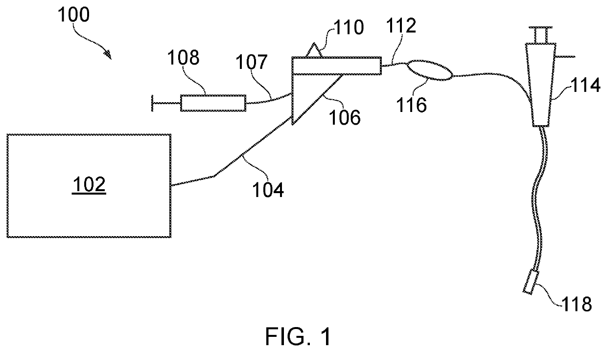
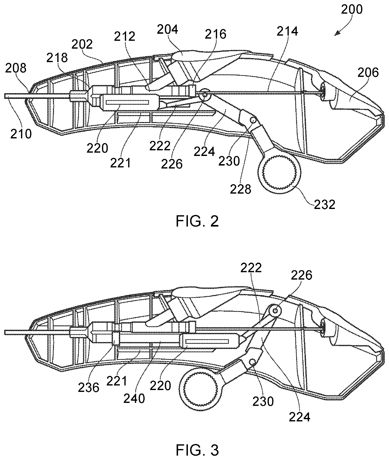
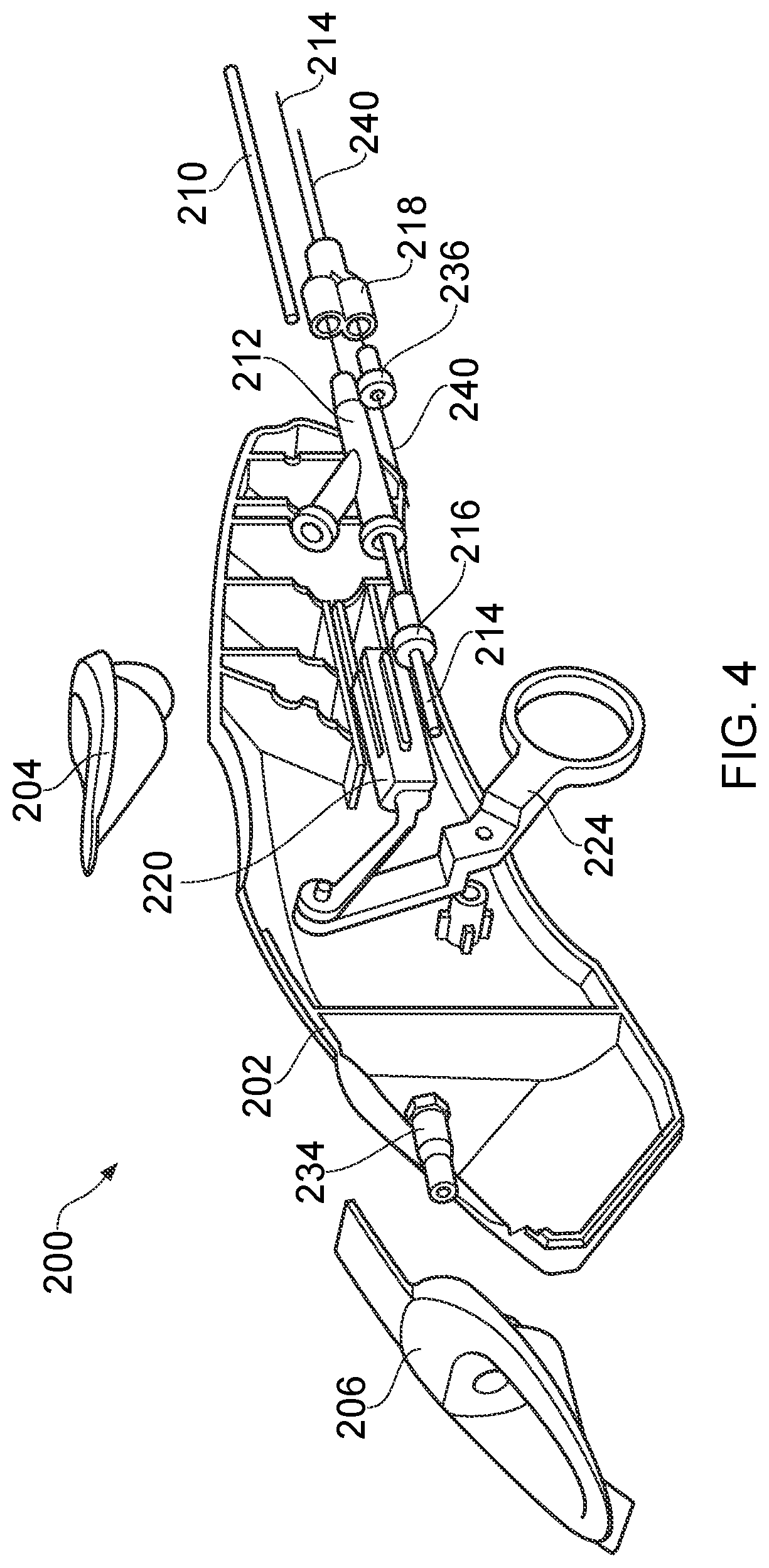
[0045]FIGS. 2, 3 and 4 show various views of an interface joint 200 that is the invention. The interface joint 200 may be used with the apparatus 100 discussed above, in place of the interface joint 106.

[0046]The interface joint 200 comprises a housing 202, e.g. formed from a rigid polymer. The housing 202 encasing the components of the interface joint 200 discussed below.

[0047]The housing 202 has a plurality of apertures in its outer surface which provide various ports for the joint.

[0048]On a top surface there is a first port for receiving a fluid supply, e.g. a syringe for injecting a liquid such as saline or hyaluronic acid. The first port has a moulded receiving element 204 mounted therein. The moulded receiving element 204 may be shaped to cooperate with a connection interface of the fluid supply to provide a secure interconnection.

[0049]At the rear (proximal end) of the housing there is a second port for receiving power from the electrosurgical generator. The second port may ...

second embodiment

[0063]FIG. 5 is a perspective view of an interface joint 300 that is the invention. The interface joint 300 comprise a housing 302. The interface joint 300 may be used with the apparatus 100 discussed above, in place of the interface joint 106 and torque transfer unit 116.

[0064]The housing 302 may be a rigid hollow casing that encloses the junctions and components discussed below. The casing may be made from moulded plastic, e.g. in two halves that are securable together, e.g. by welding or the like.

[0065]The housing 302 has a pair of ring elements 304 integrally formed on opposing sides thereof. The ring elements 304 provide finger grips for a user operating the device.

[0066]The housing 302 has a outlet port at a distal end thereof. A flexible shaft 308 extends out of the output port, whereupon it may be fed into an instrument channel of a surgical scoping device. The distal end of the housing may comprise a conical tip section 306. The tip section may be rigid. Alternatively it ma...


PUM


Abstract

An interface joint with one or both of a needle actuation mechanism or an integrated shaft rotation mechanism. The interface joint comprises a flexible shaft between a housing and an electrosurgical instrument, e.g. for conveying power and / or fluid therebetween. The needle actuation mechanism comprises an actuation rod extending out of the housing and an actuator movably mounted on the housing. The shaft rotation mechanism comprises a rotation actuator rotatably mounted on the housing and operably coupled to the flexible shaft. Providing an integrated shaft rotation mechanism may obviate the need for a separate torque transmission unit. The improved needle actuation mechanism may use a pivoting connection to enable longer needle extension distances to be achieved for a given actuation distance.

Description

CROSS-REFERENCE TO RELATED APPLICATIONS[0001]This application is a Divisional of U.S. patent application Ser. No. 16 / 632,826, filed on Jan. 21, 2020, which is a U.S. National Stage application of PCT International Application No. PCT / EP2018 / 072154, filed Aug. 15, 2018, which claims priority to United Kingdom Patent Application No. 1713173.1, filed Aug. 17, 2017. The disclosures of the prior applications are incorporated herein by reference in their entireties.FIELD OF THE INVENTION[0002]The invention relates to an electrosurgical apparatus in which an electrosurgical instrument is inserted through the instrument channel of a surgical scoping device in order to treat biological tissue located beyond a distal end of the instrument channel. In particular, the invention relates to a control device, e.g. a handle, that is located outside the surgical scoping device and used to manipulate or otherwise operate the electrosurgical instrument.BACKGROUND TO THE INVENTION[0003]Surgical resecti...

Claims


Application Information

Patent Timeline
Patent Type & Authority Applications(United States)
IPC IPC(8): A61B18/14A61B18/18
CPCA61B18/1492A61B2017/0034A61B18/1815A61B2018/00172A61B2018/00178A61B2018/00196A61B2018/00601A61B2018/00916A61B2018/1425A61B2218/002A61B2018/1412A61B2018/1861A61B18/1206A61B2018/00083A61B2017/00424A61B2018/00345A61B2018/0063A61B2018/00982A61B2018/00994
Inventor HANCOCK, CHRISTOPHER PAULMONICO, ROHANHOPKINS, HUWCRAVEN, TOMMORRIS, STEVE
Owner CREO MEDICAL LTD
Learn More