
Optical cable for emergency rush repair and emergency device using optical cable

An optical cable and light sending technology, which is applied in the field of emergency devices and emergency rescue optical cables, can solve the problems of unable to meet long-distance, long-term lighting needs, limited power, weight burden, etc., and achieve convenient climbing, easy climbing, and low attenuation constant effect

Active Publication Date: 2015-08-26
JIANGSU HUAMAI OPTOELECTRONICS TECH CO LTD +1
View PDF12 Cites 0 Cited by
  • Summary
  • Abstract
  • Description
  • Claims
  • Application Information

AI Technical Summary

Problems solved by technology

[0003] In firefighting, emergency rescue, disaster relief, scientific research and other occasions, it is often necessary to have emergency lighting technology. In the prior art, the commonly used emergency lighting generally has an irradiation distance of about 100 meters, and most of them are flashlight-shaped, and the power is quite limited, which cannot meet the long-term requirements. Distance, long-term lighting needs
On the other hand, when firefighting, emergency rescue, disaster relief, and scientific research personnel use emergency lighting facilities, they can often carry them with them, so their weight has become a burden for rescuers.

Method used


Image

  • Optical cable for emergency rush repair and emergency device using optical cable
  • Optical cable for emergency rush repair and emergency device using optical cable
  • Optical cable for emergency rush repair and emergency device using optical cable

Examples


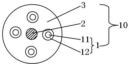
Embodiment 1

[0033] please see figure 1 , a kind of emergency rescue optical cable 10, it has four optical transmission parts 1, is characterized in that it also has the inner strength member 2, and the sheath layer 3 that covers light transmission part and inner strength member; The transmission unit 11 is composed of a protective layer 12 covering the light transmission unit.

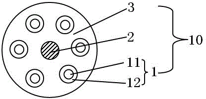
Embodiment 2

[0035] please see figure 2 , an emergency rescue optical cable 10, which has six optical transmission parts 1, is characterized in that it also has an inner strength member 2, and a sheath layer 3 covering the light transmission parts and the inner strength member; The unit 11 is composed of a protective layer 12 covering the light transmission unit.

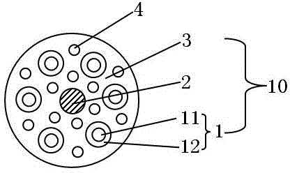
Embodiment 3

[0037] please see image 3 , an emergency rescue optical cable 10, which has six optical transmission parts 1, is characterized in that it also has an inner strength member 2, and a sheath layer 3 covering the light transmission parts and the inner strength member; The unit 11 is composed of a protective layer 12 covering the light transmission unit; it also has a plurality of outer strengthening members 4 located outside the inner strengthening member and inside the sheath layer.


PUM

PropertyMeasurementUnit
diameteraaaaaaaaaa

Abstract

The invention belongs to the technical field of emergency lighting and relates to an emergency lighting optical cable which is provided with multiple light transmission parts and is characterized by further comprising an inner reinforcer and a protective sleeve layer which wraps the light transmission parts and the inner reinforcer, wherein each light transmission part is composed of a light transmission unit and a protective layer; each protective sleeve layer is made of polyvinyl chloride or polyethylene or a composite material prepared from the following raw materials in parts by weight: 55-65 parts of polyvinyl resin, 5-10 parts of PBT resin, 10-20 parts of TPU resin, 3-5 parts of TPE resin, 3-8 parts of ABS resin, 1-3 parts of fire retardant 400A, 0.4-1 part of antioxidant1010, 0.5-1 part of white oil, 0.4-1.5 parts of PE color master batch and 3-7 parts of sodium acrylate. The invention also discloses an emergency device adopting the emergency lighting optical cable. The emergency lighting optical cable has the main beneficial effects of portability, longer extension distance, higher strength, easiness for binding and climbing ad longer product service life.

Description

[0001] This application is a divisional application of an invention patent application titled: An emergency lighting optical cable and an emergency device using the optical cable, the application number is 201410000927.5, and the application date is January 2, 2014. technical field [0002] The invention belongs to the technical field of emergency lighting, and in particular relates to an emergency rescue optical cable and an emergency device using the optical cable. Background technique [0003] In firefighting, emergency rescue, disaster relief, scientific research and other occasions, it is often necessary to have emergency lighting technology. In the prior art, the commonly used emergency lighting generally has an irradiation distance of about 100 meters, and most of them are flashlight-shaped, and the power is quite limited, which cannot meet the long-term requirements. Distance, long-term lighting needs. On the other hand, firefighting, emergency rescue, disaster reli...

Claims


Application Information

Patent Timeline
Patent Type & Authority Applications(China)
IPC IPC(8): G02B6/44
CPCG02B6/4429G02B6/443G02B6/4432
Inventor 沈群华
Owner JIANGSU HUAMAI OPTOELECTRONICS TECH CO LTD
Learn More