Method of manufacturing component
a manufacturing method and component technology, applied in the field of manufacturing components, can solve the problems of uneven heating of different parts, heat loss, and the above-mentioned method, and achieve the effect of shortening the throughput time of manufacturing components
- Summary
- Abstract
- Description
- Claims
- Application Information
AI Technical Summary
Benefits of technology
Problems solved by technology
Method used
Image
Examples
first embodiment
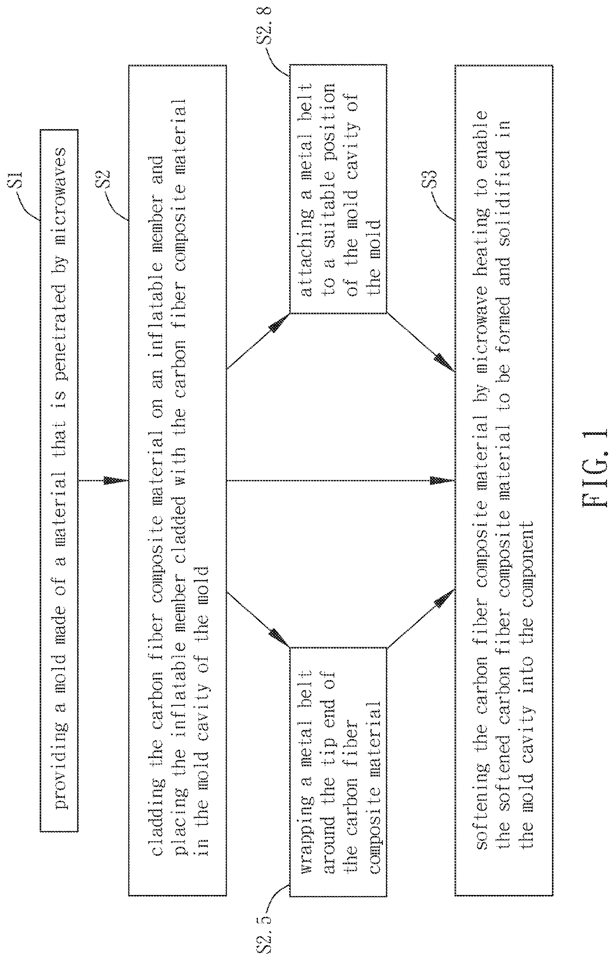
[0031]As shown in FIG. 1, a method according to the present invention is used to make a carbon fiber composite material 10 capable of absorbing electromagnetic waves in the microwave spectrum into a component (as shown in FIG. 4). In this embodiment, the component is a frame 20 of a bicycle (hereafter referred to as “frame”20). The method comprises the following steps:
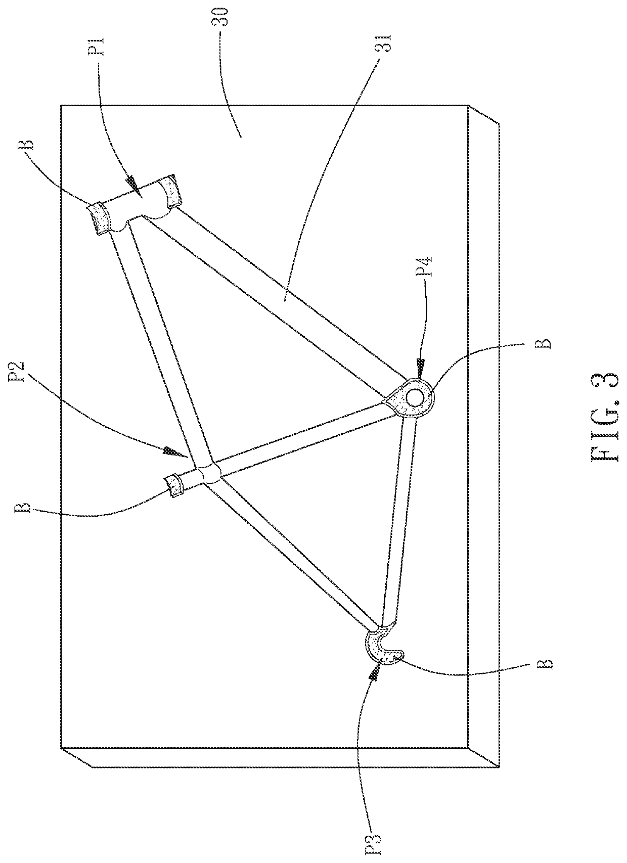
[0032]Step S1: providing a mold 30 made of a material that is penetrated by microwaves, such as Teflon, i.e., the material has a relatively low absorption rate with respect to the electromagnetic waves in the microwave spectrum. The mold 30 has a mold cavity 31 inside (as shown in FIG. 3, FIG. 3 only shows half of the mold 30). The configuration of the mold cavity 31 is complementary to the configuration of the frame 20.
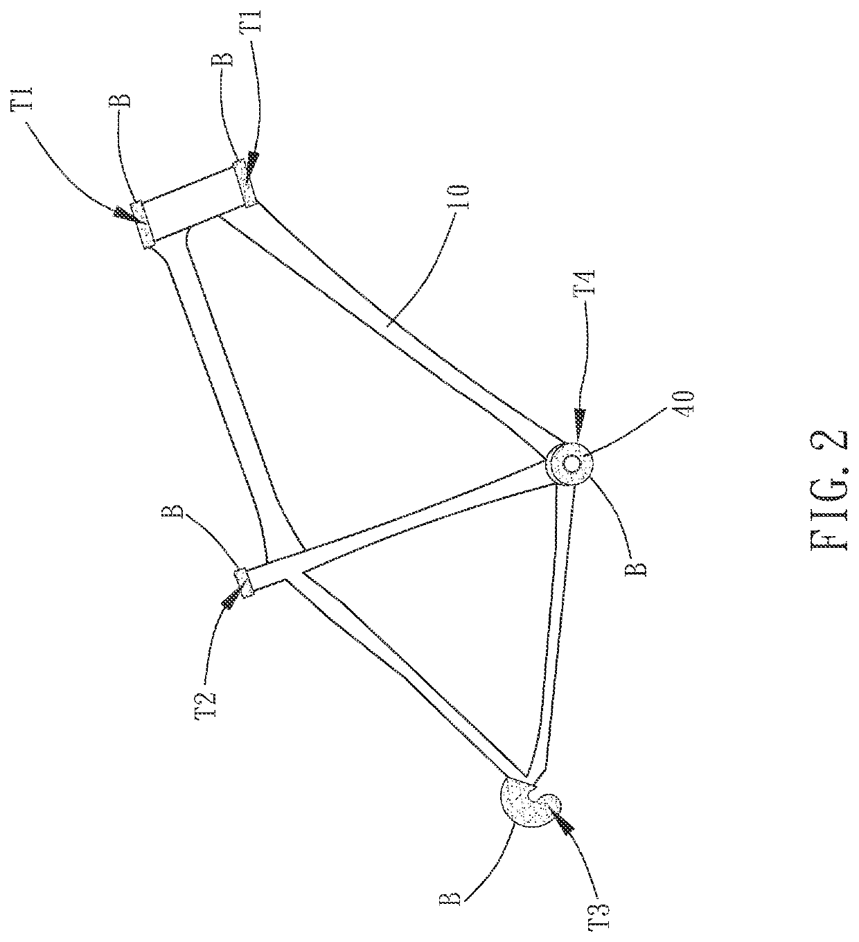
[0033]Step S2: cladding the carbon fiber composite material 10 on an inflatable member 40 (see FIG. 2) and placing the inflatable member 40 cladded with the carbon fiber composite material 10 in the mol...
second embodiment
[0037]As shown in FIGS. 6 to 14, a method according to the present invention is also used to make a carbon fiber composite material 10 capable of absorbing electromagnetic waves in the microwave spectrum into a component 1. In this embodiment, the method is used to manufacture a frame 20 of a bicycle as shown in FIG. 14. However, this embodiment is not limited to this example. The method comprises the following steps:
[0038]Step 2.1: providing a mold 30 made of a material that is penetrated by the microwaves. The mold 30 has a mold cavity 31 inside (as shown in FIG. 7, FIG. 7 only shows half of the mold 30). The mold cavity 31 is divided into a component forming area 32, a slice forming area 33, and two sleeve receiving areas 34, wherein the configuration of the component forming area 32 is complementary to the configuration of the frame 20, and the slice forming area 33 is connected with the component forming area 32 and corresponding to the middle section of the front tube 21 of th...
PUM
| Property | Measurement | Unit |
|---|---|---|
| Time | aaaaa | aaaaa |
| Diameter | aaaaa | aaaaa |
Abstract
Description
Claims
Application Information
 - R&D
- Intellectual Property
- Life Sciences
- Materials
- Tech Scout
- Unparalleled Data Quality
- Higher Quality Content
- 60% Fewer Hallucinations
Browse by: Latest US Patents, China's latest patents, Technical Efficacy Thesaurus, Application Domain, Technology Topic, Popular Technical Reports.
© 2025 PatSnap. All rights reserved.Legal|Privacy policy|Modern Slavery Act Transparency Statement|Sitemap|About US| Contact US: help@patsnap.com


