Turbine ring assembly mounted on a cross-member

a technology of cross-member and turbine ring, which is applied in the direction of machines/engines, climate sustainability, sustainable transportation, etc., can solve the problems of reducing the operations of machining the parts of the ring support structure, and achieve the reduction of manufacturing tolerances, simplified mounting of the turbine ring assembly, and reduced the operation of machining

Pending Publication Date: 2022-06-23
SN DETUDE & DE CONSTR DE MOTEURS DAVIATION S N E C M A
View PDF5 Cites 2 Cited by
  • Summary
  • Abstract
  • Description
  • Claims
  • Application Information

AI Technical Summary

Benefits of technology

[0012]The turbine ring assembly according to the invention is remarkable in particular in that the CMC ring is held directly on the turbine casing by means of a ring support structure without resorting to a ring support casing. Particularly, compared to the prior art, the assembly according to the invention is devoid of ring support casing and the radial slugs that allow holding the ring support structure on this casing are eliminated.
[0013]In addition, the ring support structure is made of several parts that are separate and independent from each other, which allows a mounting of this structure per angular sectors and no longer a crown mounting. The mounting of the turbine ring assembly is simplified and requires no tools. Furthermore, the manufacturing tolerances are less severe, the spacers making it possible to compensate for the gaps between the ring sectors, which a 360° flange cannot do. In addition, the elimination of radial slugs reduces the operations of machining the parts of the ring support structure. This results in a saving of parts and therefore a reduction of the weight and cost of the assembly.

Problems solved by technology

In addition, the elimination of radial slugs reduces the operations of machining the parts of the ring support structure.

Method used


Image

  • Turbine ring assembly mounted on a cross-member
  • Turbine ring assembly mounted on a cross-member

Examples


Embodiment Construction

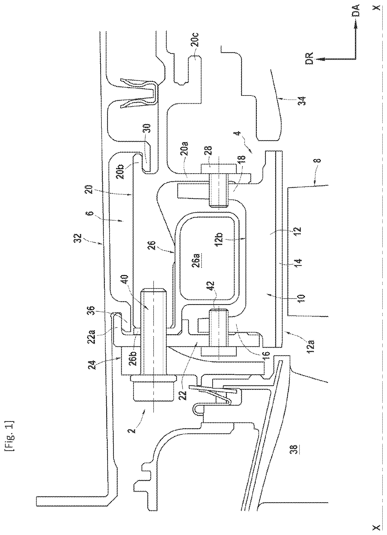
[0022]FIG. 1 represents, in longitudinal section, a turbine ring assembly 2 according to the invention.

[0023]This assembly 2 comprises in particular a turbine ring 4 made of ceramic matrix composite material (CMC) centered on a longitudinal axis XX and a metal ring support structure 6. The turbine ring 4 surrounds a set of turbine blades 8.

[0024]Furthermore, the turbine ring 4 is formed of a plurality of angular ring sectors 10 which are placed end to end circumferentially to form a ring. In FIG. 1, the arrow DA indicates the axial direction of the turbine ring while the arrow DR indicates the radial direction of the turbine ring.

[0025]Each angular ring sector 10 has a section substantially in the form of an inverted Pi (or π) with a base 12 provided with an inner face 12a which defines an angular portion of the inner face of the turbine ring and which is typically provided with an abradable coating layer 14 also acting as a thermal and environmental barrier.

[0026]Two lugs—namely an...


PUM


Abstract

A turbine ring assembly extending about an axis, includes a plurality of ring sectors made of ceramic matrix composite material forming a turbine ring and a ring support structure held by a turbine casing, each ring sector including a base from which an upstream lug and a downstream lug spaced axially from each other extend radially outwardly, the ring support structure including a spacer having a clamp against which the downstream lug of the ring sectors is held, a first upstream flange against which the upstream lug of the ring sectors is held, and upstream of the first upstream flange, a second upstream flange for absorbing forces against which the first upstream flange is held.

Description

TECHNICAL FIELD[0001]The invention relates to a turbine ring assembly for a turbomachine in which the s assembly comprises a plurality of angular ring sectors placed end to end to form a turbine ring made of ceramic matrix composite material.[0002]One field of application of the invention is in particular that of aeronautical gas turbine engines.PRIOR ART[0003]The ceramic matrix composite materials, or CMC, are known to retain their mechanical properties at high temperatures, which makes them able to constitute elements of a hot structure.[0004]In aeronautical gas turbine engines, the improvement in the efficiency and the reduction of some polluting emissions lead to seeking operation at ever higher temperatures. In the case of entirely metallic turbine ring assemblies, it is necessary to cool all the elements of the assembly and particularly the turbine ring which is subjected to very hot flows, typically higher than the temperature tolerable by the metal material. This cooling has...

Claims


Application Information

Patent Timeline
Patent Type & Authority Applications(United States)
IPC IPC(8): F01D25/28F01D25/12
CPCF01D25/28F01D25/12F01D11/08F01D25/246F05D2240/11F05D2300/6033Y02T50/60
Inventor QUENNEHEN, LUCIEN HENRI JACQUESDANIS, ANTOINE CLAUDE MICHEL ETIENNEDUFFAU, CLÉMENT JEAN PIERREJARROSSAY, CLÉMENTTABLEAU, NICOLAS PAUL
Owner SN DETUDE & DE CONSTR DE MOTEURS DAVIATION S N E C M A
Why Eureka
Try Eureka