
Optical system and plane spectroscopic device

Pending Publication Date: 2022-06-23
CANON KK
View PDF5 Cites 0 Cited by
  • Summary
  • Abstract
  • Description
  • Claims
  • Application Information

AI Technical Summary

Benefits of technology

The present disclosure is about an optical system that can divide a light into different parts. It includes multiple reflecting surfaces that guide the light to different positions on a curved-surface mirror. Another reflecting surface then reflects the light that has been guided by the first surface. The number of reflective surfaces on which the light is incident is the same as the number of ways in which the light is divided, resulting in a precise and accurate division of the light. This optical system can be used to create a detailed and accurate image of an object plane.

Problems solved by technology

If an original image is more finely divided, higher-resolution information is obtainable, but it is not easy to one-dimensionally array divided images in a limited space.
However, the transmittance of the optical fiber is not completely uniform, and it is difficult to extract original light information in a uniform state, due to, for example, a polarization state of light changes because of a curvature.
Thus, there is no optical fiber optimum for a wide wavelength, and it is difficult in principle to efficiently perform plane spectral dispersion in a wide wavelength band.
However, even if the divisional number is set to about several tens in consideration of manufacturing process, such as adjustment, because it is necessary to extremely accurately arrange the respective mirrors in terms of position and accuracy, the structure becomes spatially large, resulting in a difficulty in incorporating the mirrors into general equipment with an equivalent number of divisions.

Method used


Image

  • Optical system and plane spectroscopic device
  • Optical system and plane spectroscopic device
  • Optical system and plane spectroscopic device

Examples


Embodiment Construction

[0013]Hereinafter, preferred exemplary embodiments of the present disclosure will be described in detail with reference to the accompanying drawings.

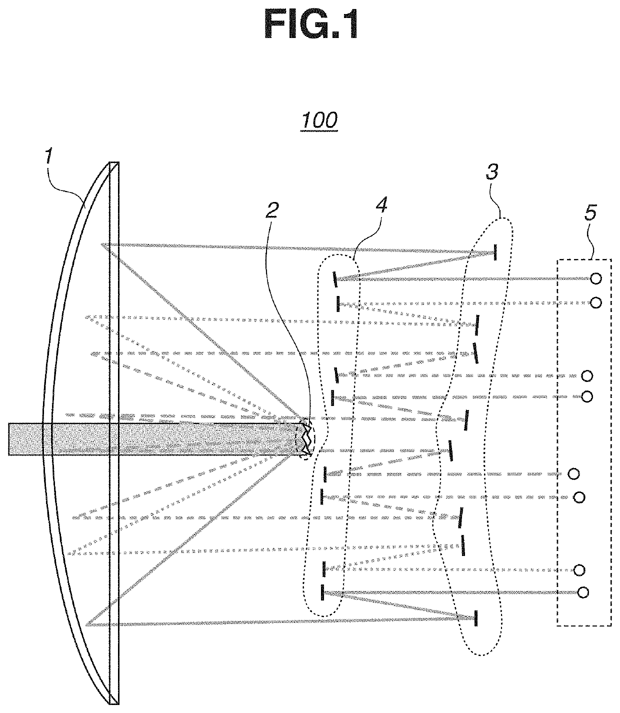
[0014]A first exemplary embodiment of the present disclosure will be described below. FIG. 1 illustrates a view of a field division optical system 100 of the first exemplary embodiment. The field division optical system 100 is an optical system that divides a light flux from a side of an object plane. As illustrated in FIG. 1, the field division optical system 100 roughly includes four groups of mirrors in order from an incident direction of an incident light flux to be divided. The field division optical system 100 includes a first reflecting portion 1, a second reflecting portion 2, a third reflecting portion 3, and a fourth reflecting portion 4.

[0015]The first reflecting portion 1 is a curved-surface mirror having a curved reflective surface, and is provided with an opening through which the light flux from the object plane passes or...


PUM


Abstract

An optical system to divide a light flux from an object plane includes a first curved-surface mirror, and second, third, and fourth reflecting portions. The second reflecting portion divides and reflects light flux from the first curved-surface mirror to respective different positions on the first curved-surface mirror as first light fluxes. The third reflecting portion reflects, as third light fluxes, the first light fluxes. The fourth reflecting portion reflects the third light fluxes from the third reflecting portion. A number of reflective surfaces of each of the third and fourth reflecting portions on which the first and third light fluxes are incident is the same as a division number in the dividing of the light flux into the second light fluxes. The first and third light fluxes are reflected by the respective third and fourth reflecting portions to be image-formed so that divided images of the object plane are formed.

Description

BACKGROUNDField[0001]The present exemplary embodiments relate to an optical system and a plane spectroscopic device.Description of the Related Art[0002]When a dynamic phenomenon is analyzed in detail, it is highly useful to obtain information about wavelength (energy) by simultaneously and temporally performing spectral dispersion on images, and it is important in all fields involving chemical reactions. To simultaneously perform spectral dispersion on image information, which is two-dimensional, it is necessary to convert a two-dimensional image into a one-dimensional image because a general detector supports two-dimensional or less dimensional images and thus the number of dimensions into which wavelength information is expanded increases. Thus, a plane division optical system is an important element in plane spectral division which is collectively performed at substantially the same timing (Japanese Patent Application Laid-Open No. 2012-237647).[0003]If an original image is more ...

Claims


Application Information

Patent Timeline
IPC IPC(8): G02B17/06G02B27/14G01N21/35
CPCG02B17/0652G01N2201/0636G01N21/35G02B27/14G02B27/1013G01J3/021G01J3/0243G01J3/2803G02B27/143
Inventor SUKEGAWA, TAKASHI
Owner CANON KK
Learn More