Distance member for connecting wind turbine blade shear webs

a technology of distance member and shear web, which is applied in the manufacture of final products, machines/engines, other domestic articles, etc., can solve the problems of compromising the strength of bond, affecting the performance of the final product, and causing overly thick bond lines

Active Publication Date: 2022-06-30
LM WIND POWER R&D HOLLAND BV +2
View PDF5 Cites 0 Cited by
  • Summary
  • Abstract
  • Description
  • Claims
  • Application Information

AI Technical Summary

Benefits of technology

[0014]The respective upper and lower adhesive joints are typically formed between the respective inner surface of the shell half and the respective shear web, usually the mounting flange of the shear web, by applying adhesive to these surfaces and then applying pressure. It was found that the method of the present invention allows for an improved alignment of these bonding surface due to allowing the shear webs to move towards each other when closing the blade. It was also found that this approach yields thinner bond lines and to a more constant bond line thickness between the shear webs and the inner surface of the shell halves.
[0038]The wind turbine blade preferably also comprises one or more distance plugs that are inserted between the respective mounting flange of the first and / or the second shear web and the respective inner surface of the upwind and / or downwind shell parts, the distance plugs extending through the entire thickness of a bond line between the mounting flange and the inner surface, thereby assisting in providing a reliable and durable bond.

Problems solved by technology

However, one of the challenges involved in this approach is the provision of an accurate amount of adhesive between the flanges and the shell half.
Too little adhesive may compromise the strength of the bond, whereas too much adhesive will create an overly thick bond line.
In view of ever-increasing blade sizes, achieving such bond thickness can be difficult, owing to tolerance overlaps of shell and web moulds, components, and to the effect of shell repairs.
Moreover, with blades and blade components getting bigger, it becomes more difficult to obtain a full control of the shear web movement: Hence, the final arrangement of shear web is challenging, and a full control of the final web bond line thickness remains elusive.

Method used


Image

  • Distance member for connecting wind turbine blade shear webs
  • Distance member for connecting wind turbine blade shear webs
  • Distance member for connecting wind turbine blade shear webs

Examples


Embodiment Construction

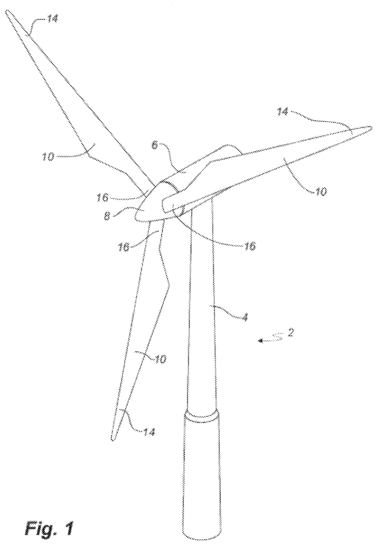
[0059]FIG. 1 illustrates a conventional modern upwind wind turbine 2 according to the so-called “Danish concept” with a tower 4, a nacelle 6 and a rotor with a substantially horizontal rotor shaft. The rotor includes a hub 8, and three blades 10 extending radially from the hub 8, each having a blade root 16 nearest the hub and a blade tip 14 furthest from the hub 8.

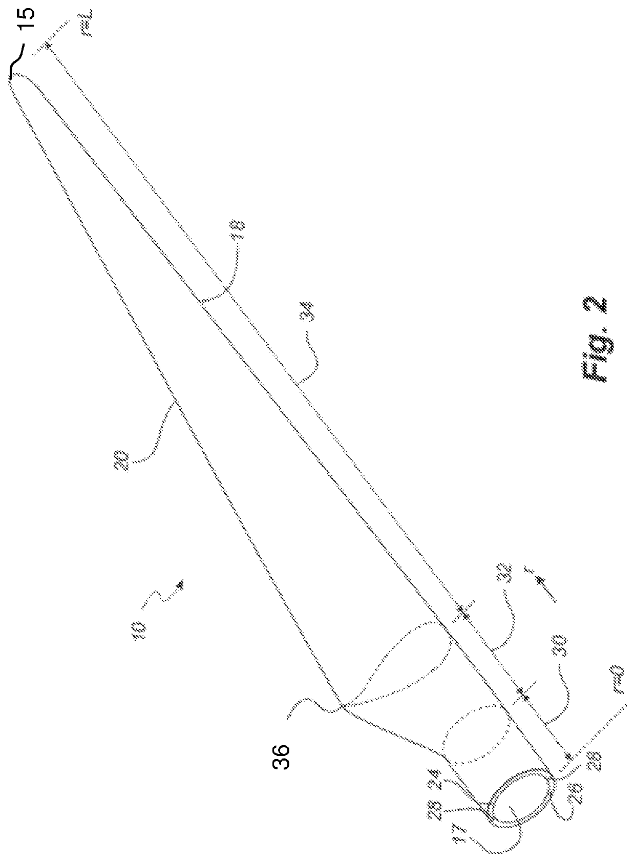
[0060]FIG. 2 shows a schematic view of an exemplary wind turbine blade 10. The wind turbine blade 10 has the shape of a conventional wind turbine blade with a root end 17 and a tip end 15 and comprises a root region 30 closest to the hub, a profiled or an airfoil region 34 furthest away from the hub and a transition region 32 between the root region 30 and the airfoil region 34. The blade 10 comprises a leading edge 18 facing the direction of rotation of the blade 10, when the blade is mounted on the hub, and a trailing edge 20 facing the opposite direction of the leading edge 18.

[0061]The airfoil region 34 (also called t...


PUM

PropertyMeasurementUnit
lengthaaaaaaaaaa
thicknessaaaaaaaaaa
thicknessaaaaaaaaaa

Abstract

The present invention relates to a wind turbine blade and a method for its manufacture. A lower shell part and an upper shell part are provided, each shell part having a leading edge and a trailing edge. A first shear web and a second shear web for connecting an inner surface of the lower shell part with an inner surface of the upper shell part are provided. The first shear web and the second shear web are connected by a first distance member in a chordwise direction. The first distance member is arranged for accommodating a variable chordwise distance between said first shear web and said second shear web. The first shear web and the second shear web are placed in the lower shell part and the upper shell part is mounted.

Description

FIELD OF THE INVENTION[0001]The present invention relates to a method for manufacturing a wind turbine blade and to a wind turbine blade obtainable by said method.BACKGROUND OF THE INVENTION[0002]Wind power provides a clean and environmentally friendly source of energy. Wind turbines usually comprise a tower, generator, gearbox, nacelle, and one or more rotor blades. The wind turbine blades capture kinetic energy of wind using known airfoil principles. Modern wind turbines may have rotor blades that exceed 90 meters in length.[0003]Wind turbine blades are usually manufactured by forming two shell parts or shell halves from layers of woven fabric or fibre and resin. Wind turbine blades of fibre-reinforced polymer are usually manufactured in moulds, where the pressure side and the suction side of the blade are manufactured separately by arranging glass fibre mats and / or other fibre-reinforcement material, such as carbon fibre, in each of the two mould parts. The two shell halves are u...

Claims


Application Information

Patent Timeline
Patent Type & Authority Applications(United States)
IPC IPC(8): B29C65/48F03D1/06
CPCB29C65/4825B29L2031/085F03D1/0675B29C65/48B29C65/4835B29C66/112B29C66/131B29C66/532B29C66/545B29C66/543B29D99/0028B29C65/7829B29C65/782B29C66/61B29C66/636B29C66/8227B29C66/8262Y02E10/72Y02P70/50F05B2230/23F05B2260/301
Inventor NIELSEN, MICHAEL WENANIZHURAVLOV, PAVELGANGAVARAM PANDARINATH, SURESH BABU
Owner LM WIND POWER R&D HOLLAND BV
Why Eureka
Try Eureka