Cervical distraction/implant delivery device

a technology of implant delivery device and cervical disc, which is applied in the field of cervical disc distraction/implant delivery device, can solve the problem of at least one of the plurality of teeth being dislocated

Pending Publication Date: 2022-07-07
PROVIDENCE MEDICAL TECH
View PDF2 Cites 5 Cited by
  • Summary
  • Abstract
  • Description
  • Claims
  • Application Information

AI Technical Summary

Benefits of technology

The patent text describes an implant to stabilize or fuse a facet joint in the spine, which can help reduce pain and restore function. The implant has a head that can be expanded to increase the size of the joint and maintain it in a stable condition. The technique involves inserting the implant into the joint and expanding it to increase the space between the vertebrae. This expands the joint and reduces pain for patients with degenerative disc disease or spinal injuries.

Problems solved by technology

In this embodiment, the handle can be in communication with the distraction mechanism and actuation of the handle can cause distraction thereof.
Actuation of the elongate member can cause distraction of at least one of the plurality of pairs of teeth.

Method used


Image

  • Cervical distraction/implant delivery device
  • Cervical distraction/implant delivery device
  • Cervical distraction/implant delivery device

Examples


first embodiment

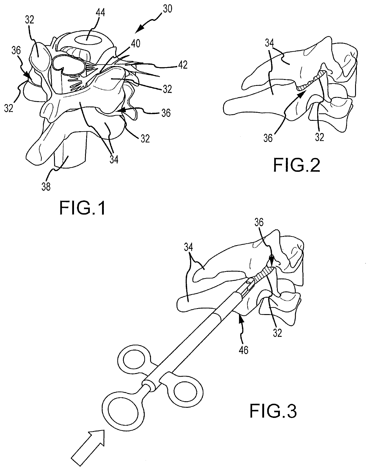
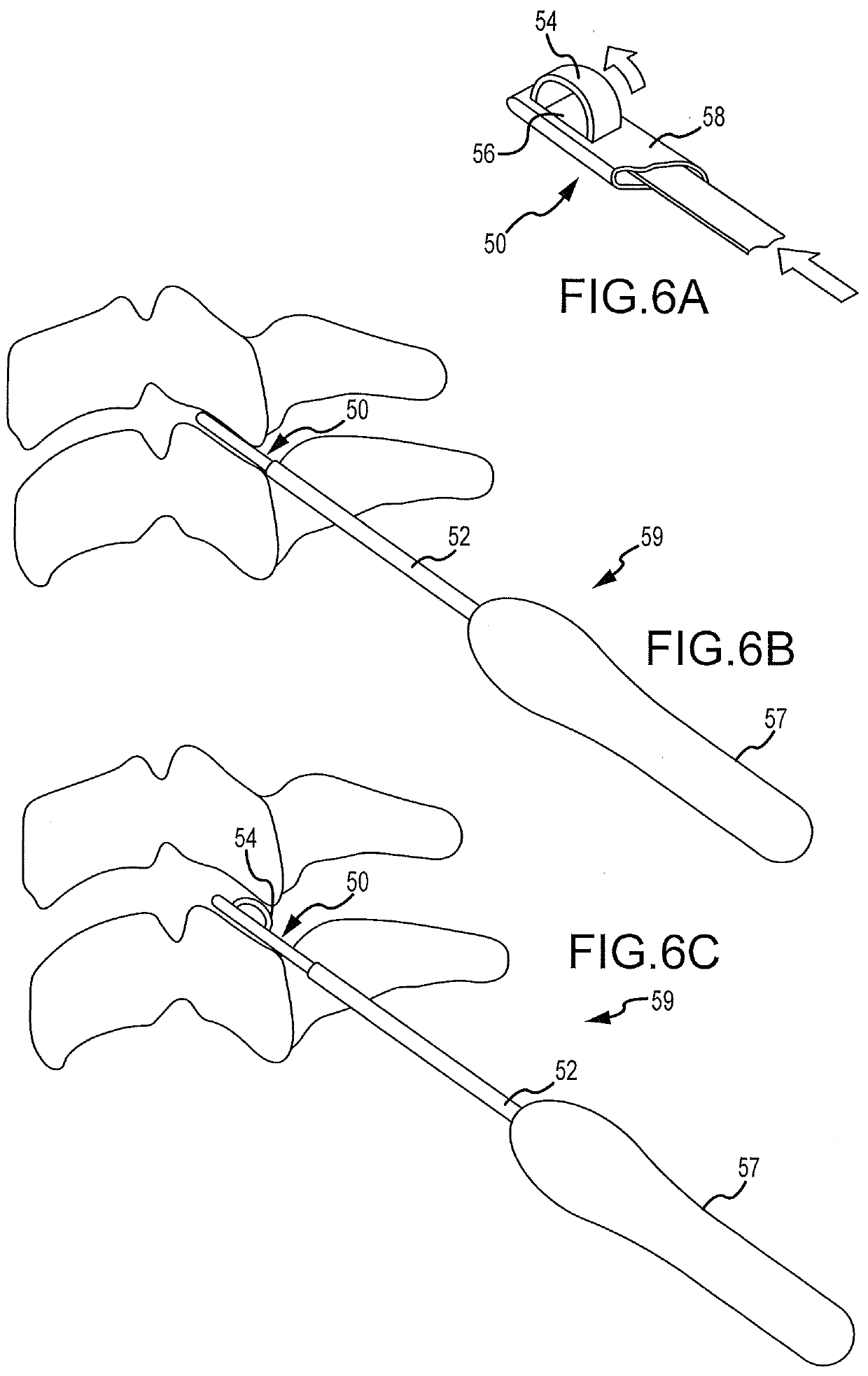
[0116]a delivery tool 59 in accordance with the present invention is shown in FIGS. 6A-6C. It will there be seen, pursuant to the above description with any and / or all of the embodiments of the present invention to be disclosed hereafter, a delivery tool can be inserted down the working cannula, for example of the access system described previously, which can be docked in a facet joint 36. The distal end of the delivery tool can be positioned at the anterior aspect of the joint 36 and the surgeon can apply energy to the delivery tool to create separation and distraction of the facet joint 36. The separation can occur in both the vertical and horizontal planes of the joint 36 resulting in vertical distraction and forward / anterior translation of the superior vertebrae relative to the inferior vertebrae. The facet joint distraction and forward translation can cause an increase in foramina) area and thus reduce nerve root compression and associated symptoms.

[0117]Referring to the first ...

second embodiment

[0121]the invention is shown in FIGS. 7A-7C. A handle 67 and cannula 62 can be provided as described previously. In this embodiment, a distraction mechanism 60 in the form of a collapsible box can be positioned on the distal end of the delivery tool 69. The distraction mechanism 60 can include upper 66 and lower 64 walls as well as end walls 68 with the walls 64, 66, 68 being pivotally connected so the device is movable between a flattened position as shown in FIG. 76 to an expanded position as shown in FIG. 7A. A locking mechanism can also be provided such as a cross-brace or other device for maintaining the mechanism 60 in an expanded position once expanded.

[0122]Fixation mechanisms 70 can be provided on the exterior surface of both upper 64 and lower 66 walls. These fixation mechanisms 70 can be in the form of 1) Aggressive shark teeth, 2) Cleats, and / or 3) Roughened pores. The aggressive shark teeth (as shown in FIG. 7A) can have a directional orientation positioned to achieve o...

fourth embodiment

[0126]a delivery tool 89 in accordance with the present invention is shown in FIGS. 9A-9C. In this embodiment of the invention, the distraction mechanism 88 can have a diamond-shaped or oblong distraction head 90 made from a somewhat rigid but flexible band or strip of material. The mechanism 88 can include an actuator in the form of an elongate member 92 extending longitudinally there through that is adapted to draw the opposing ends 94, 96 of the distraction head 90 together. The elongate member 92 can be a threaded member adapted to draw the ends 94, 96 of the head 90 together by interaction with a female member 91. The interaction can be via a screw action with a female threaded member as shown. Alternatively, the elongate member 92 can be a toothed member adapted to draw the ends 94, 96 of the head 90 together via a ratcheting action with a female ratchet member similar to that of a cable tie. In either case, the elongate member 92 can extend through the head 90 of the distract...


PUM


Abstract

Systems for distracting a facet joint and positioning a permanent implant in the joint are disclosed. The implants serve to retain a distracted position of the facet joint which is achieved with positioning of the leading end of a distraction tool in the facet joint and then distracting or enlarging the joint a desired amount. The permanent implant could be part of the distraction mechanism which can be separated from the delivery tool once the joint has been distracted or an auxiliary implant may be positioned before the distraction mechanism is removed from the distracted joint. The permanent implants can be solid, mechanical devices that may have fixation means thereon to hold them in place or injected fluids such as hydrogels or fluids confined within balloons.

Description

CROSS REFERENCE TO RELATED APPLICATION[0001]The present application is a continuation of U.S. application Ser. No. 15 / 488,989 filed Apr. 17, 2017 and entitled Cervical Distraction / Implant Delivery Device (the '989 application). The '989 application is a continuation of U.S. application Ser. No. 13 / 949,042 filed Jul. 23, 2013, and entitled Cervical Distraction / Implant Delivery Device (the '042 application), now U.S. Pat. No. 9,622,874. The '042 application is a continuation of U.S. application Ser. No. 12 / 559,193 filed Sep. 14, 2009 and entitled Cervical Distraction / Implant Delivery Device (the '193 application), now U.S. Pat. No. 8,512,347. The '193 application is a continuation-in-part of U.S. application Ser. No. 12 / 455,814 filed Jun. 5, 2009, and entitled Facet Joint Implants and Delivery Tools (the '814 application), now U.S. Pat. No. 8,361,152. The '814 application is a continuation-in-part of U.S. application Ser. No. 12 / 317,682 filed Dec. 23, 2008, and entitled Facet Joint Im...

Claims


Application Information

Patent Timeline
Patent Type & Authority Applications(United States)
IPC IPC(8): A61F2/44A61B17/56A61B17/70A61B17/88A61B17/02
CPCA61F2/442A61B17/562A61B17/7062A61B17/7064A61B2017/00557A61B17/8822A61F2/4405A61B17/025A61F2220/0041A61B17/7065A61B17/8855A61B2017/0256A61B2090/037A61F2/4455A61F2/446A61F2/447A61F2/4611A61F2002/30205A61F2002/30227A61F2002/3023A61F2002/30266A61F2002/30281A61F2002/30433A61F2002/30579A61F2002/30878A61F2002/30879A61F2002/30884A61F2002/30892A61F2002/30894A61F2002/4627A61F2002/30599A61F2002/30405A61F2002/30571A61F2002/30622A61F2002/30841
Inventor MCCORMACK, BRUCE M.SMITH, JEFFREY D.
Owner PROVIDENCE MEDICAL TECH
Why Eureka
Try Eureka