Engine control device

Active Publication Date: 2022-07-07
TOYOTA JIDOSHA KK
View PDF4 Cites 0 Cited by
  • Summary
  • Abstract
  • Description
  • Claims
  • Application Information

AI Technical Summary

Benefits of technology

[0011]Note that the engine control device according to the aspect, the catalyst air-fuel ratio correction process may be performed by setting a correction amount of the target air-fuel ratio based on an engine speed, an engine load factor, and a supercharging pressure. The supercharging pressure in a state where the engine spe

Problems solved by technology

Moreover, due to an influence of the change, an emission of the engine may be deteriorated.
When the lean combustion continues, the catalyst device cannot eventually store excess oxygen anymore, and an outflow of the exhaust gas containing the excess oxygen, a so-called a lean failure, occurs.
When the rich combustion continues, the catalyst device even

Method used


Image

  • Engine control device
  • Engine control device
  • Engine control device

Examples


first embodiment

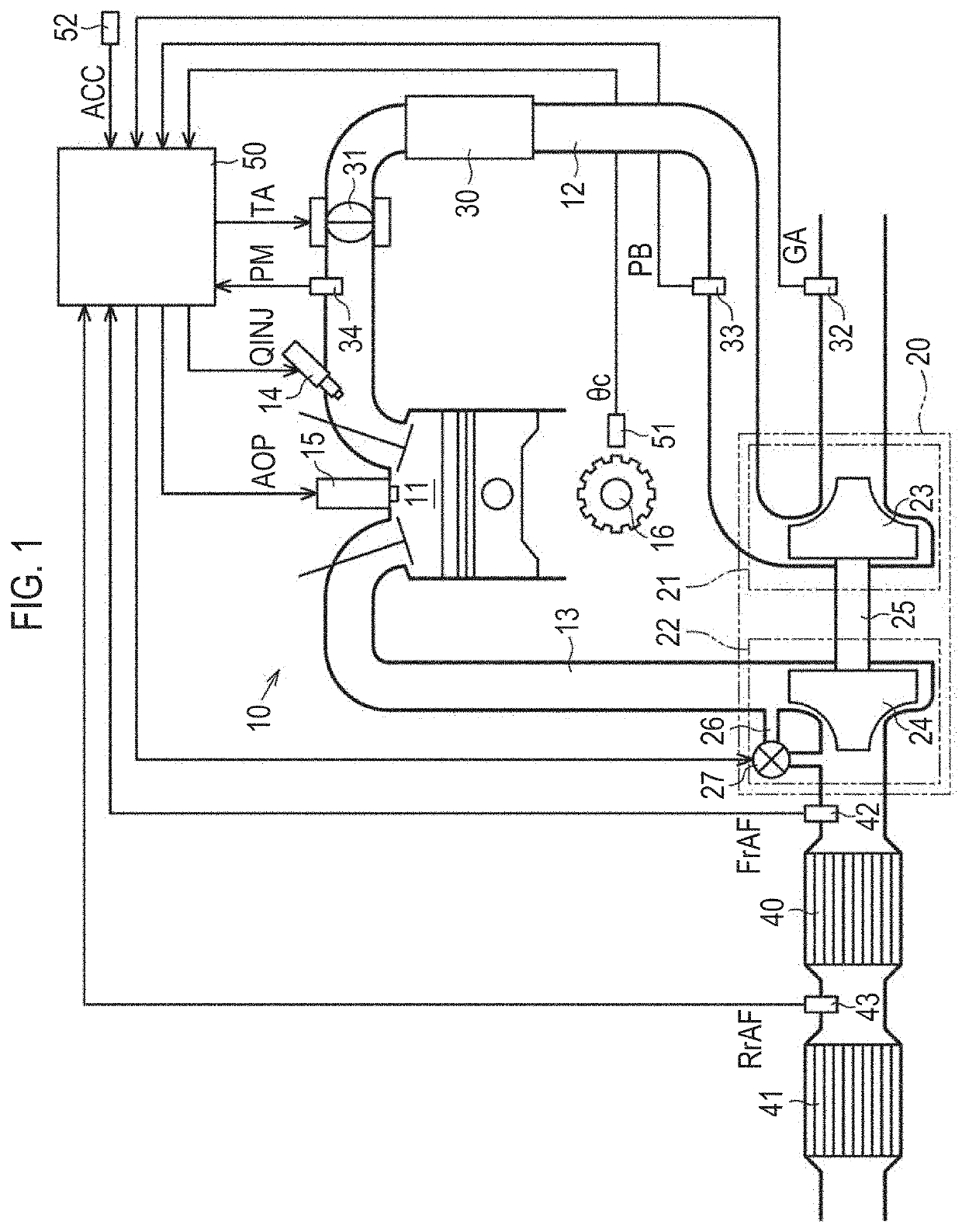
[0028]Hereinafter, a first embodiment of an engine control device will be described in detail with reference to FIGS. 1 to 12. The engine control device according to the present embodiment is applied to an engine equipped with a turbocharger mounted on a vehicle.

[0029]Configuration of Engine Control Device

[0030]First, a configuration of an engine 10 to which the engine control device according to the present embodiment is applied will be described with reference to FIG. 1. The engine 10 includes a combustion chamber 11 in which an air-fuel mixture is combusted. Further, the engine 10 includes an intake passage 12 that is an introduction passage of an intake gas into the combustion chamber 11 and an exhaust passage 13 that is an emission passage of an exhaust gas from the combustion chamber 11. Note that the engine 10 includes a plurality of cylinders, and each cylinder has the individual combustion chamber 11. FIG. 1 shows solely one of a plurality of the combustion chambers 11. The...

second embodiment

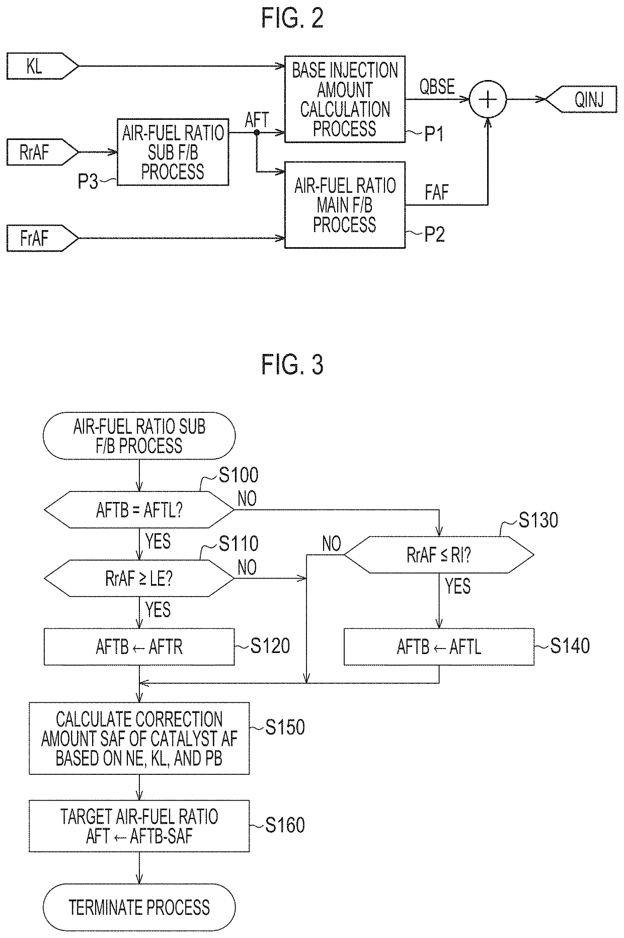
[0083]Hereinafter, a second embodiment of the engine control device will be described in detail with reference to FIG. 13. Note that in the present embodiment, the same reference characters are given to the configurations common to the embodiment described above, and detailed description thereof will be omitted. In the present embodiment, a process content of the air-fuel ratio sub F / B process P3 in the first embodiment is changed, and other points are the same as those in the first embodiment.

[0084]FIG. 13 is a flowchart of the air-fuel ratio sub F / B process P3 performed by the engine control device 50 according to the present embodiment. Note that steps S100 to S140 of FIG. 13 are the same as that of the first embodiment shown in FIG. 3. That is, also in the present embodiment, the occurrence of the lean failure and the rich failure is confirmed based on the rear air-fuel ratio RrAF, and the value of the base target air-fuel ratio AFTB is alternately switched between the lean side...

third embodiment

[0090]Hereinafter, a third embodiment of the engine control device will be described in detail with reference to FIGS. 14 to 15. Note that in the present embodiment, the same reference characters are given to the configurations common to the embodiment described above, and detailed description thereof will be omitted.

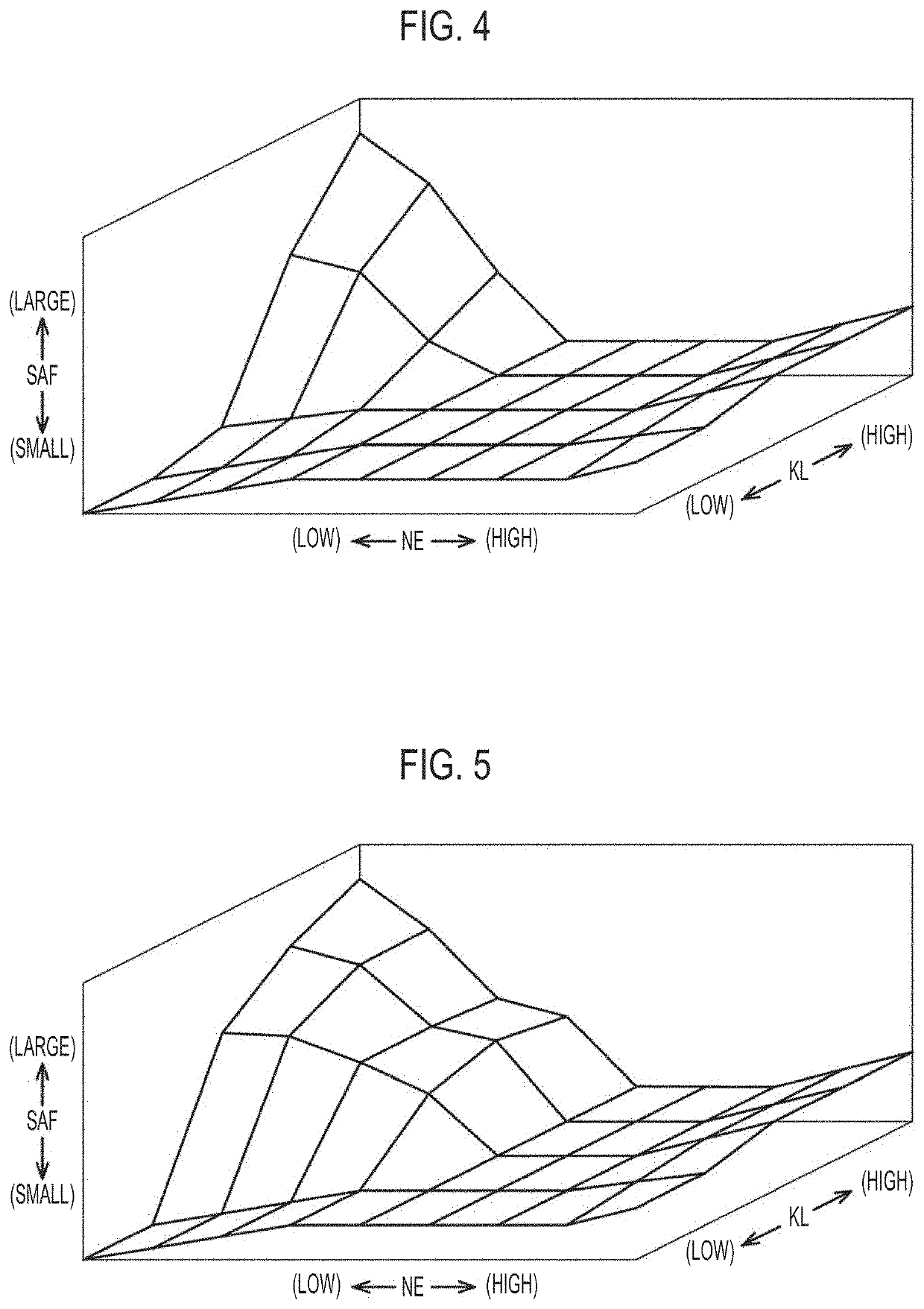
[0091]FIG. 14 shows a flowchart of the calculation process of the correction amount SAF of the catalyst AF in the present embodiment. In the present embodiment, the calculation process of FIG. 14 is performed instead of the processes of steps S150 and S160 of FIG. 3.

[0092]In the calculation of the correction amount SAF of the catalyst AF in the present embodiment, first, in step S300, a value of a base correction amount SAFB based on the engine speed NE and the engine load factor KL is calculated. Subsequently, in step S310, the value of a WGV opening degree correction coefficient KS is calculated based on the WGV opening degree. Moreover, in step S320, the product obta...


PUM


Abstract

An engine control device is configured to perform an air-fuel ratio main feedback process based on an output of a front air-fuel ratio sensor, an air-fuel ratio sub feedback process of alternately switching a target air-fuel ratio between a rich side target air-fuel ratio and a lean side target air-fuel ratio based on an output of a rear air-fuel ratio sensor, and a catalyst air-fuel ratio correction process of, when an opening degree of a wastegate valve is large, correcting the target air-fuel ratio to be the air-fuel ratio on the rich side with respect to the air-fuel ratio when the opening degree is small.

Description

CROSS-REFERENCE TO RELATED APPLICATION[0001]This application claims priority to Japanese Patent Application No. 2021-001537 filed on Jan. 7, 2021, incorporated herein by reference in its entirety.BACKGROUND1. Technical Field[0002]The present disclosure relates to an engine control device.2. Description of Related Art[0003]In engines, such as an on-vehicle engine, there is an engine on which a three-way catalyst is supported and that includes a catalyst device for exhaust gas cleaning having an oxygen storage capacity. Further, in the engines including such a catalyst device, there is an engine in which air-fuel ratio sensors are installed on an upstream side and a downstream side of the catalyst device in an exhaust passage, respectively. Moreover, as a control device of such an engine, there is an engine that performs an air-fuel ratio control through two feedback processes of main feedback based on an output of the air-fuel ratio sensor on the upstream side of the catalyst device ...

Claims


Application Information

Patent Timeline
IPC IPC(8): F02D41/14F02B37/18F01N3/10F01N13/00
CPCF02D41/1454F02B37/18F02D2200/101F01N13/008F01N3/101F02D41/0007F01N3/0864F01N5/04F01N9/00F01N2240/36F01N2430/06F01N2560/025F01N2560/14F01N2900/08F02D41/1475Y02T10/12
Inventor NAKAGOSHI, SHINICHIYOSHIOKA, SHINJI
Owner TOYOTA JIDOSHA KK
Why Eureka
Try Eureka