
Horizontal Directional Reaming

a reaming and horizontal technology, applied in the direction of directional drilling, earth drilling, drilling machines and methods, etc., can solve the problems of reducing the crushing effect of the reaming cone, causing the reaming cone to create mechanical inefficiency, and significant mechanical inefficiency, so as to achieve the effect of efficient crushing

Active Publication Date: 2022-07-21
QUANTA ASSOC
View PDF40 Cites 3 Cited by
  • Summary
  • Abstract
  • Description
  • Claims
  • Application Information

AI Technical Summary

Benefits of technology

The patent text is about a method of drilling the earth, ground, or rock using drill bits or reamer heads. The goal is to create a crushing effect, where each tooth pushes against the rock. The rotational movement, combined with the high-speed injection of drilling fluid, helps to evacuate the crushed rock pieces, leaving the surface of the rock clean for the next tooth to repeat the process. The patent aims to improve the efficiency of Horizontal Directional Drilling (HDD) equipment for achieving this desired crushing effect.

Problems solved by technology

The prior art cones and split-bit reamer create mechanical inefficiency at the cones.
This creates significant mechanical inefficiency.
As a consequence of this inefficiency, the teeth successively and relatively closer to the tip of the cones have imperfect contact with the earth, ground, or rock which causes teeth to skid or drag over the rock, inefficiently scratching or scrapping its surface and often ineffectively drilling or crushing the earth, ground, or rock.
The inefficiency may be especially disruptive in situations where the geological material being reamed comprises rock or hard rock.
The mechanical inefficiency giving rise to scratching or scraping action, instead of a crushing action, causes teeth successively and relatively closer to the tip of the cones to become flat (worn) sooner than the gauge teeth.
The lifetime of the reamer and the ROP of the reamer are negatively affected by this mechanical inefficiency.
Additionally, the greater the distance between the center of rotation of a cone and the center of rotation of the reamer, the greater or more pronounced is the mechanical inefficiency.

Method used


Image

  • Horizontal Directional Reaming
  • Horizontal Directional Reaming
  • Horizontal Directional Reaming

Examples


Embodiment Construction

[0029]The description that follows includes exemplary apparatus, methods, techniques, and instruction sequences that embody techniques of the inventive subject matter. However, it is understood that the described embodiments may be practiced without these specific details.

[0030]Referring to FIG. 4, the hole 52 is reamed by the reamer 50 to make a larger hole 54. A pilot hole (not shown or potentially 52) is drilled to begin a crossing. The pilot hole may be reamed after drilling to make an intermediate or relatively larger hole 52. The intermediate hole 52 is reamed against walls 53 by reamer 50 to make a larger hole 54. The reamer 50 was dispatched from the rig 61 opposite drilling rig 60 and drills the arcuate path or crossing 54 through the earth 10 and may cross beneath an obstacle 12 such as, for example, a body of water, a transportation way, etc.

[0031]FIG. 5 shows an exploded view of an exemplary embodiment of an improved reamer head 30 and split-bit reamer arm 34. The improv...


PUM


Abstract

The disclosure relates to embodiments of horizontal directional drilling equipment and methods for horizontal directional drilling techniques including a reamer head comprising a frustoconical body, wherein the frustoconical body defines a cavity configured to receive at least one bearing; and a plurality of teeth mounted to the frustoconical body. An imaginary apex of the frustoconical body is superimposed on the centerline of a reamer or reaming apparatus for reaming of an underground arcuate path. In another embodiment the reamer head is a progressive independently segmented reaming head. A plurality reaming heads are mounted to a reaming apparatus for reaming of an underground arcuate path.

Description

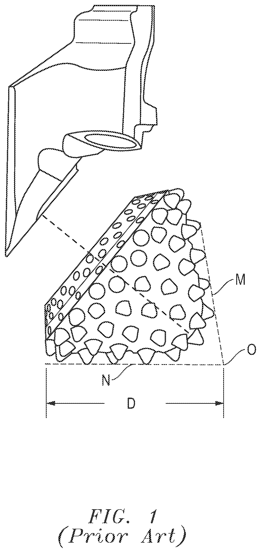
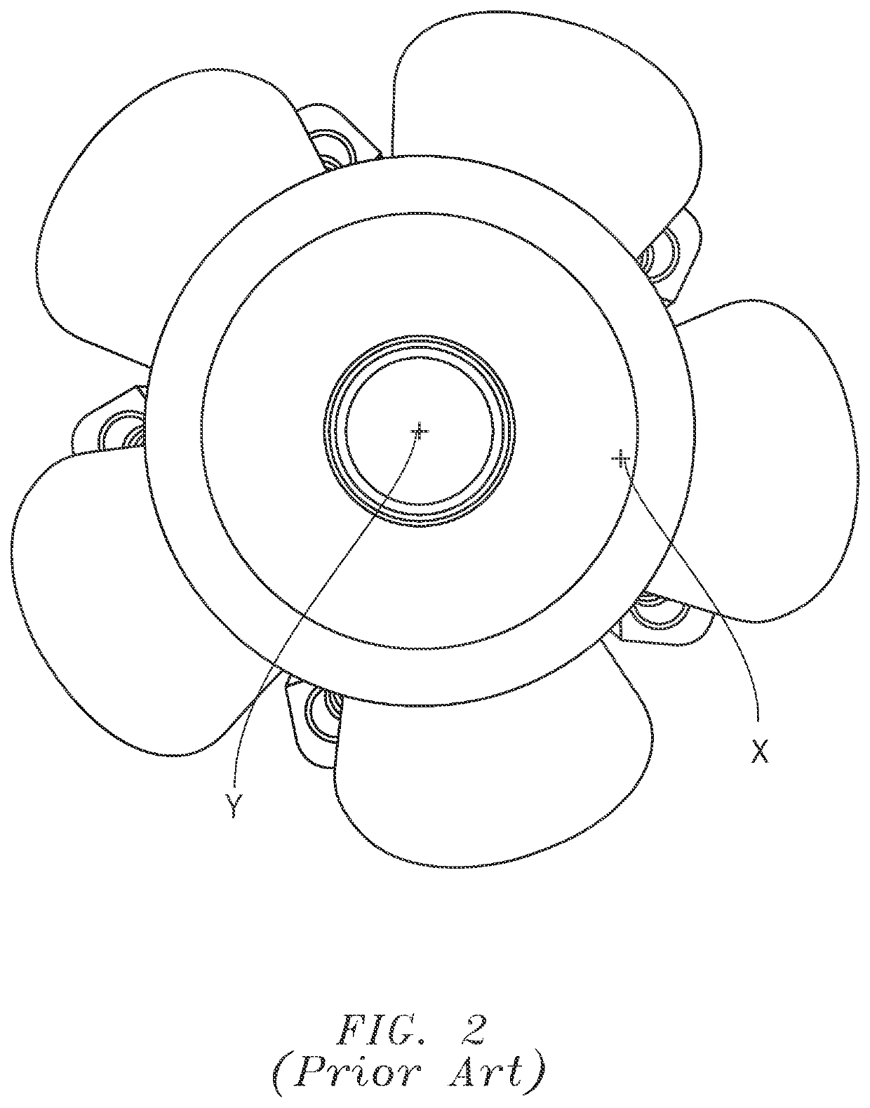
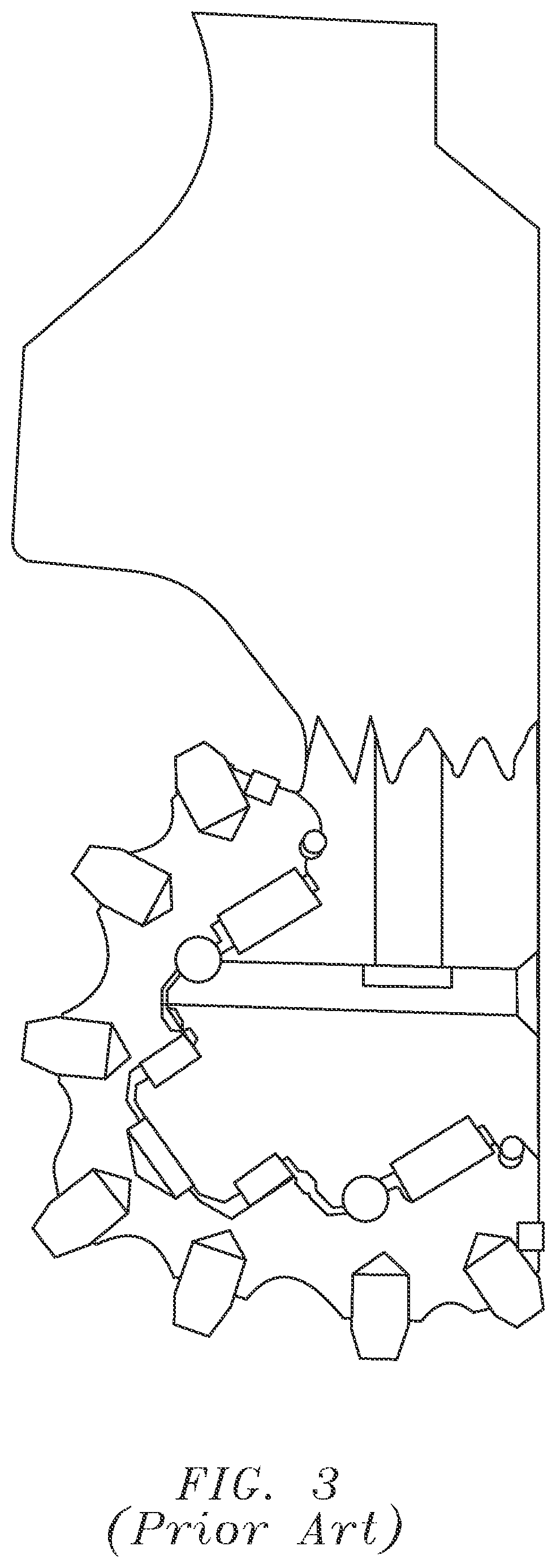
TECHNICAL FIELD[0001]The disclosure relates to the field of horizontal directional drilling or reaming techniques and equipment for drilling holes or boreholes for installation of pipe underground or under obstacles, such as a body of water.BACKGROUND[0002]Cone-shaped drill bits or cones or cutters have been used to make bore or hole enlargement tools called reamers or hole openers. A split-bit reamer is a type of reamer featuring cones or cone drill bits. The split-bit reamer is a tool often of larger diameter and is of particular use in horizontal directional drilling applications.[0003]Some examples of prior art cone drill bits and split-bit reamers are shown in FIG. 1, FIG. 2 and FIG. 3.[0004]FIG. 1 shows a typical drill bit third (i.e. of a tri-bit drill head) or reamer cone and arm / leg, which is cutting element with an arm and a rotating cone. The intersection of the dashed lines M & N shows the center of rotation O for the cone along the tool axis of rotation or axle. The typ...

Claims


Application Information

Patent Timeline
IPC IPC(8): E21B7/28E21B7/04E21B10/26E21B10/62
CPCE21B7/28E21B10/62E21B10/265E21B7/046E21B10/28
Inventor GUERRA, PABLOSTEPH, JASON
Owner QUANTA ASSOC
Learn More