
Lighting device comprising a light emitting filament

Pending Publication Date: 2022-07-21
SIGNIFY HLDG BV
View PDF2 Cites 0 Cited by
  • Summary
  • Abstract
  • Description
  • Claims
  • Application Information

AI Technical Summary

Benefits of technology

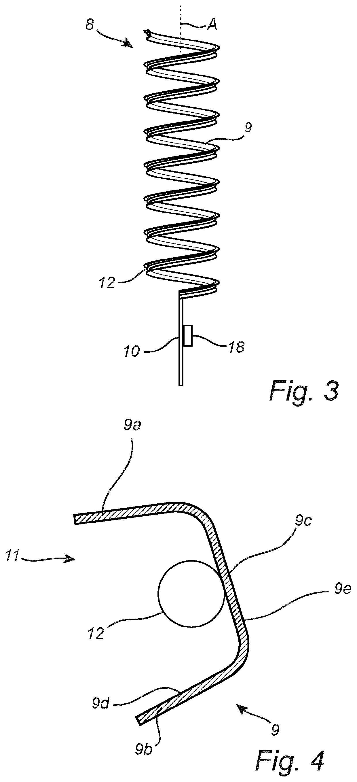
The present invention is a lighting device that uses a flexible filament and a reflector to emit light in a specific pattern. This design is cost-effective and simple in comparison to conventional solutions. The reflector acts as a support for the filament, eliminating the need for a separate support structure. The path of the reflector is designed in a spiral shape or a meander shape to improve the light distribution. The technical effects of the invention include improved glare reduction, efficient lighting distribution, and versatility in design options.

Problems solved by technology

Conventional solutions for achieving a desired emission pattern, such as providing the lighting device with various types of light-reflecting or light-blocking screens or the like, are typically more complicated structurally, and hence to manufacture.

Method used


Image

  • Lighting device comprising a light emitting filament
  • Lighting device comprising a light emitting filament
  • Lighting device comprising a light emitting filament

Examples


Embodiment Construction

[0036]The present invention will now be described more fully hereinafter with reference to the accompanying drawings, in which currently preferred embodiments of the invention are shown. The present invention may, however, be embodied in many different forms and should not be construed as limited to the embodiments set forth herein; rather, these embodiments are provided for thoroughness and completeness, and fully convey the scope of the present invention to the skilled person.

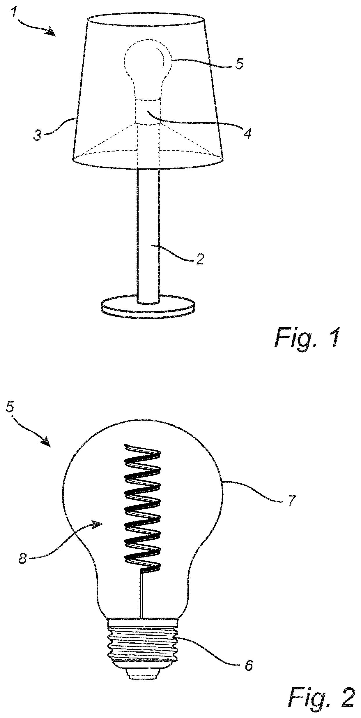
[0037]FIG. 1 shows an example of a luminaire 1. The luminaire 1 illustrated in FIG. 1 is a table lamp. The luminaire 1 may be of a different type in a different example, such as a wall-mounted or ceiling-mounted luminaire, and the luminaire may be intended for outdoor illumination instead of indoor illumination like the table lamp in FIG. 1. The luminaire 1 here comprises a base 2, a screen 3 and a connection 4 which in this case is a lightbulb socket. The luminaire 1 further comprises a light bulb 5 mounted ...


PUM


Abstract

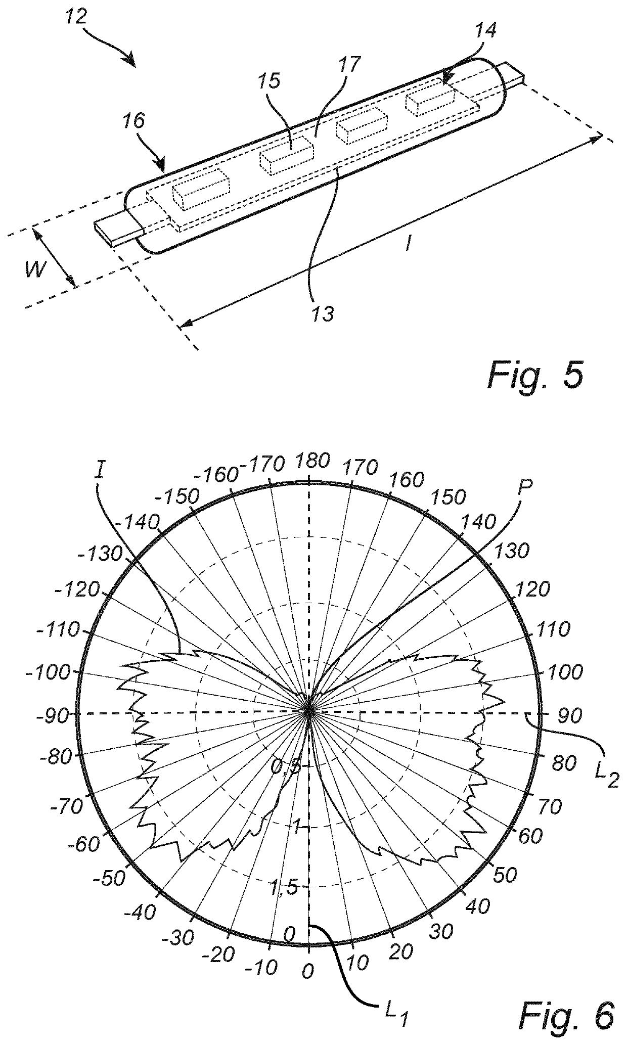
There is disclosed alighting device (8) comprising: at least one light-emitting filament comprising (12) a plurality of solid-state light sources (14); and an elongated reflector (9) arranged to reflect light emitted by the light-emitting filament (12), wherein the reflector (9) has a longitudinal groove (11) in which the light-emitting filament (12) is arranged such that the reflector (9) and the at least one light-emitting filament (12) extend longitudinally along a common path, and wherein said path is curved in three dimensions. A light bulb (5) comprising the lighting device (8) and a luminaire (1) comprising the lighting device (8) are also disclosed. The lighting device (8) can be produced cost-efficiently and adapted to conform well to a predetermined emission pattern.

Description

FIELD OF THE INVENTION[0001]The present invention relates to a lighting device comprising a light-emitting filament based on solid-state lighting technology.BACKGROUND OF THE INVENTION[0002]Light-emitting filaments based on solid-state lighting technology are used in a variety of lighting applications. An example is the light-emitting diode (LED) lamp disclosed in CN204554464U, which has a spiral-shaped LED filament mounted on a cylindrical or conical heat conducting mechanism. While the LED lamp disclosed CN204554464U, and similar lighting devices with LED filaments, are suitable for their intended use, there is currently much interest in further developing the use of light-emitting filaments in lighting applications. For example, it would be desirable to develop new solutions for providing lighting devices with different kinds of emission patterns.SUMMARY OF THE INVENTION[0003]An object of the present invention is to provide an improved or alternative lighting device with one or m...

Claims


Application Information

Patent Timeline
IPC IPC(8): F21K9/232F21K9/68F21V7/00
CPCF21K9/232F21Y2115/10F21V7/005F21K9/68F21V23/0435F21Y2107/10F21Y2113/10H05B45/3574H05B45/20Y02B20/30
Inventor VAN BOMMEL, TIESANSEMS, JOHANNES PETRUS MARIAHIKMET, RIFAT ATA MUSTAFABUKKEMS, PETER JOHANNES MARTINUS
Owner SIGNIFY HLDG BV
Learn More