Recursion-based design for suppressing inter-fiber cross-talk in multi-core fibers

a cross-talk suppression and cross-fiber technology, applied in the direction of optical waveguide light guide, optical waveguide dielectric elimination, instruments, etc., can solve problems such as problematic inter-waveguide cross-talk, and achieve the effect of maximizing the localization of the eigensta

Pending Publication Date: 2022-07-21
PENN STATE RES FOUND
View PDF0 Cites 0 Cited by
  • Summary
  • Abstract
  • Description
  • Claims
  • Application Information

AI Technical Summary

Benefits of technology

[0009]In an exemplary embodiment, a waveguide array includes: a plurality of waveguides. Each waveguide comprises a core embedded in a cladding adjacent the core. Each waveguide has a waveguide length and a waveguide propagation constant, the waveguide propagation constant for each waveguide being defined by any one or combination of a refractive index of the core, a thickness of the core, and a refractive index of the cladding. A configuration of waveguide propagation constants is formed in the transverse plane, each of the propagation constants in the configuration being uniform along a length of the waveguide array. The configuration of waveguide propagation constants causes light propagating along the length of the waveguide array to propagate in a non-diffuse manner. The configuration of waveguide propagation constants being formed by detuning the plurality of waveguides in an iterative manner, wherein each iteration includes an adjustment of the propagation constants of the plurality of waveguides. Increasing the number of iterations causes the waveguide array to maintain non-diffuse propagation of light over increasingly larger propagation distances and causes the configuration of waveguide propagation constants to approach a fractal structure, the fractal structure being a configuration of waveguide propagation constants that maximizes localization of the eigenstates of a waveguide array.

Problems solved by technology

Unfortunately, this leads to an increase in the mode overlap of adjacent waveguides causing them to couple and producing problematic interwaveguide crosstalk.

Method used


Image

  • Recursion-based design for suppressing inter-fiber cross-talk in multi-core fibers
  • Recursion-based design for suppressing inter-fiber cross-talk in multi-core fibers
  • Recursion-based design for suppressing inter-fiber cross-talk in multi-core fibers

Examples


Embodiment Construction

[0034]The following description is of exemplary embodiments that are presently contemplated for carrying out the present invention. This description is not to be taken in a limiting sense, but is made merely for the purpose of describing the general principles and features of various aspects of the present invention. The scope of the present invention is not limited by this description.

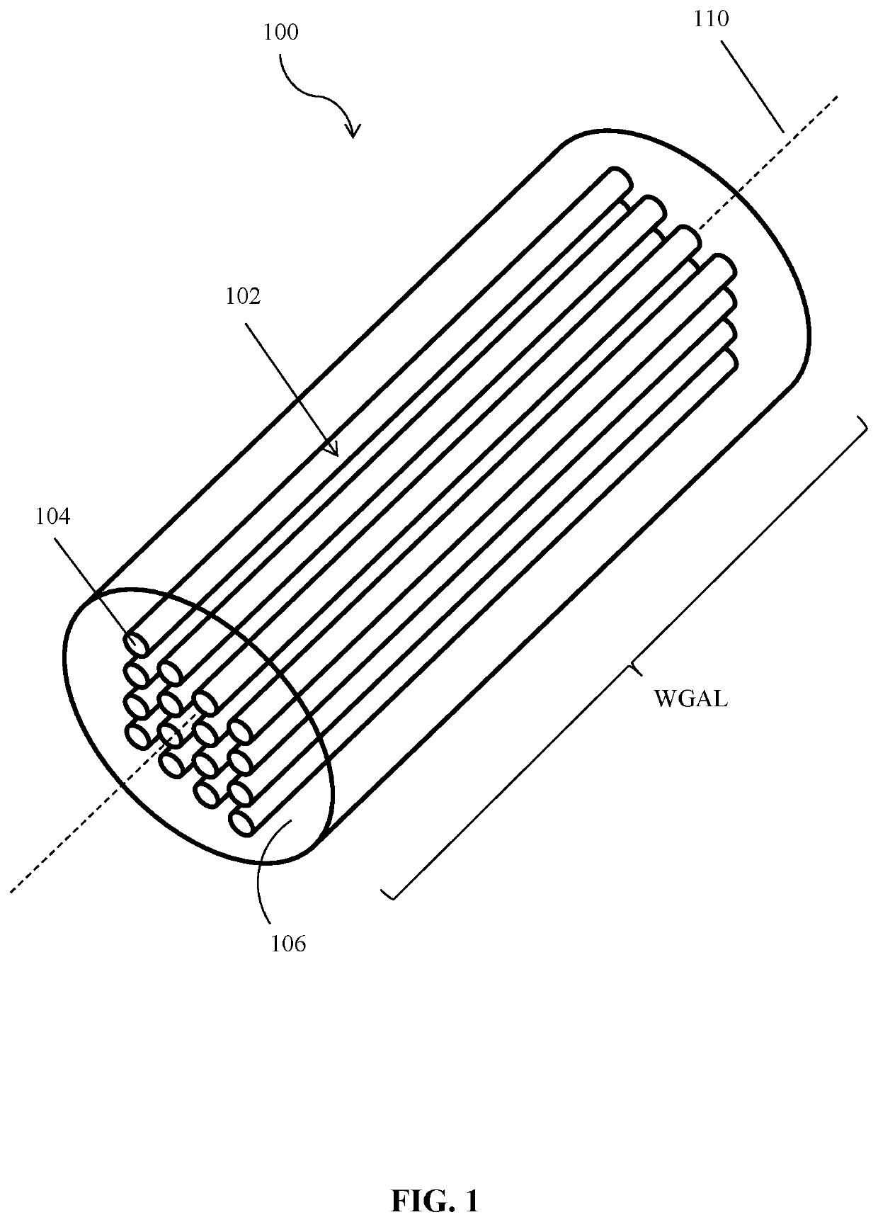
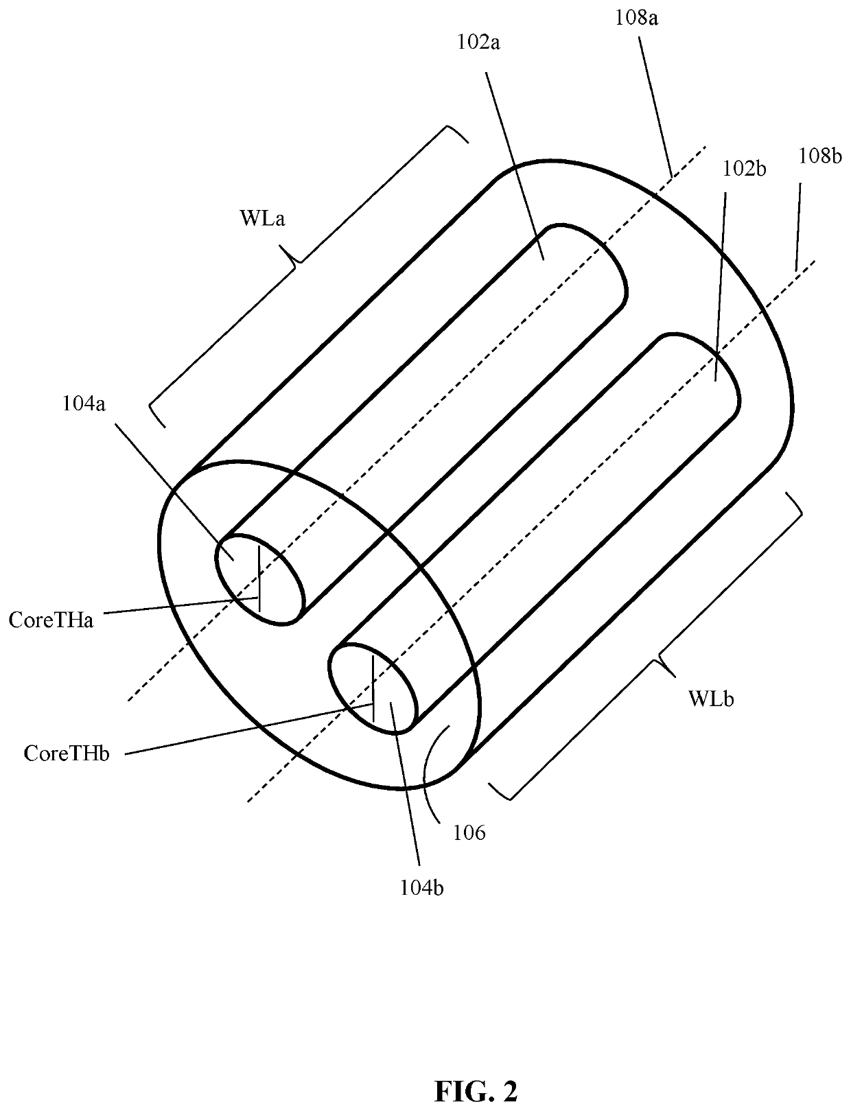
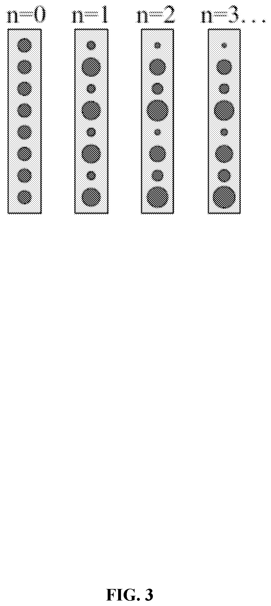
[0035]Referring to FIGS. 1-5, embodiments relate to generating a configuration of waveguide propagation constants constructed via a recursive detuning process performed on a waveguide array 100. The configuration of waveguide propagation constants yields a waveguide array with eigenstates (also called “supermodes” of the waveguide array) that influence the propagation of light through the waveguide array.

[0036]The waveguide array 100 can be configured to have a plurality of waveguides 102. A detuning process can be performed on the waveguides 102 by adjusting the propagation constant (e.g., by adjusti...


PUM


Abstract

Embodiments relate to generating a configuration of waveguide propagation constants formed in a waveguide array system. The configuration of propagation constants can be made via a recursive detuning process that produces approximations to a fractal structure designed to maximally localize eigenstates of a waveguide array. The eigenstates being maximally localized enables strong suppression of crosstalk between the waveguides. Performing more detuning iterations can produce a configuration of propagation constants that better approximates the fractal structure and suppresses crosstalk over larger distances.

Description

CROSS-REFERENCE TO RELATED APPLICATIONS[0001]This application is related to and claims the benefit of U.S. Provisional Application No. 62 / 868,627, filed on Jun. 28, 2019, the entire contents of which is incorporated herein by reference.STATEMENT REGARDING FEDERALLY SPONSORED RESEARCH OR DEVELOPMENT[0002]This invention was made with government support under Grant Nos. DMS1620218 and ECCS1509546 awarded by the National Science Foundation. The Government has certain rights in the invention.FIELD OF THE INVENTION[0003]Embodiments relate to generating a configuration of waveguide propagation constants in a waveguide array system, the configuration being made via a recursive detuning process that is designed to approximate a fractal structure that maximally localizes eigenstates (“supermodes”) of a waveguide array.BACKGROUND OF THE INVENTION[0004]The ability to transmit light through an array of closely packed waveguides while minimizing interwaveguide coupling can be beneficial for appli...

Claims


Application Information

Patent Timeline
Patent Type & Authority Applications(United States)
IPC IPC(8): G02B6/02G02B27/00H04B10/2507
CPCG02B6/02042H04B10/2507G02B27/0012
Inventor RECHTSMAN, MIKAEL CALEBGUGLIELMON, JONATHANCHEN, KEVIN PENG
Owner PENN STATE RES FOUND
Why Eureka
Try Eureka