
Motor

Pending Publication Date: 2022-07-21
LG INNOTEK CO LTD
View PDF0 Cites 0 Cited by
  • Summary
  • Abstract
  • Description
  • Claims
  • Application Information

AI Technical Summary

Benefits of technology

This patent describes a way to easily align and prevent movement of a magnet on the surface of a hollow shaft. By using small protrusions on the shaft, the magnet can be more precisely guided, and the cover of the motor can be made thinner, which improves motor performance. The protrusions can be easily formed through embossing or punching, and a knurling structure can prevent the magnet from escaping. Overall, this patent provides a more efficient and effective way to use magnets in motors and other applications.

Problems solved by technology

In this case, the hollow shaft has a problem of difficulty in aligning positions of the magnets.
This is because it is difficult to form guides for aligning the magnets due to a process of machining the hollow shaft.
When there are no guides, which guide the magnets, on the shaft, and when the magnets are overmolded, a problem of misalignment of the magnet may occur.
In addition, when the magnets are surrounded by a can or adhesive member, there is a risk of movement of the magnet.
When the adhesive is used, there is a problem in that a long time is required for curing.
In addition, when the magnets are overmolded, a problem of misalignment of the magnet may occur, and there is a problem in that it is difficult to check the misalignment.
In addition, in the case of overmolding, since a thickness is large, there is a difficulty in securing a gap with respect to the stator.

Method used


Image

  • Motor
  • Motor
  • Motor

Examples


Embodiment Construction

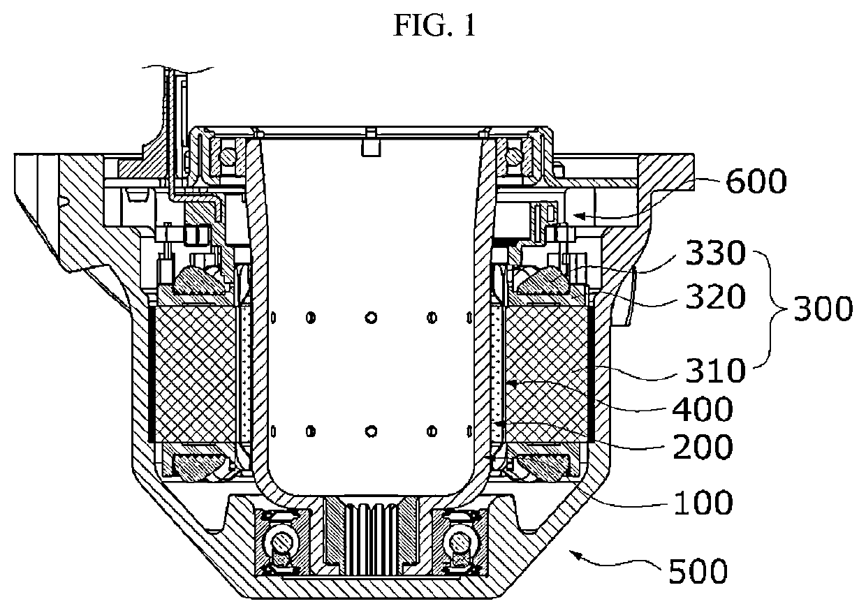
[0064]Hereinafter, exemplary embodiments of the present invention will be described in detail with reference to the accompanying drawings.

[0065]However, the technical spirit of the present invention is not limited to some embodiments which will be described and may be realized using various other embodiments, and at least one component of the embodiments may be selectively coupled, substituted, and used to realize the technical spirit within the range of the technical spirit.

[0066]In addition, unless clearly and specifically defined otherwise by context, all terms (including technical and scientific terms) used herein can be interpreted as having customary meanings to those skilled in the art, and meanings of generally used terms, such as those defined in commonly used dictionaries, will be interpreted by considering contextual meanings of the related technology.

[0067]In addition, the terms used in the embodiments of the present invention are considered in a descriptive sense and no...


PUM


Abstract

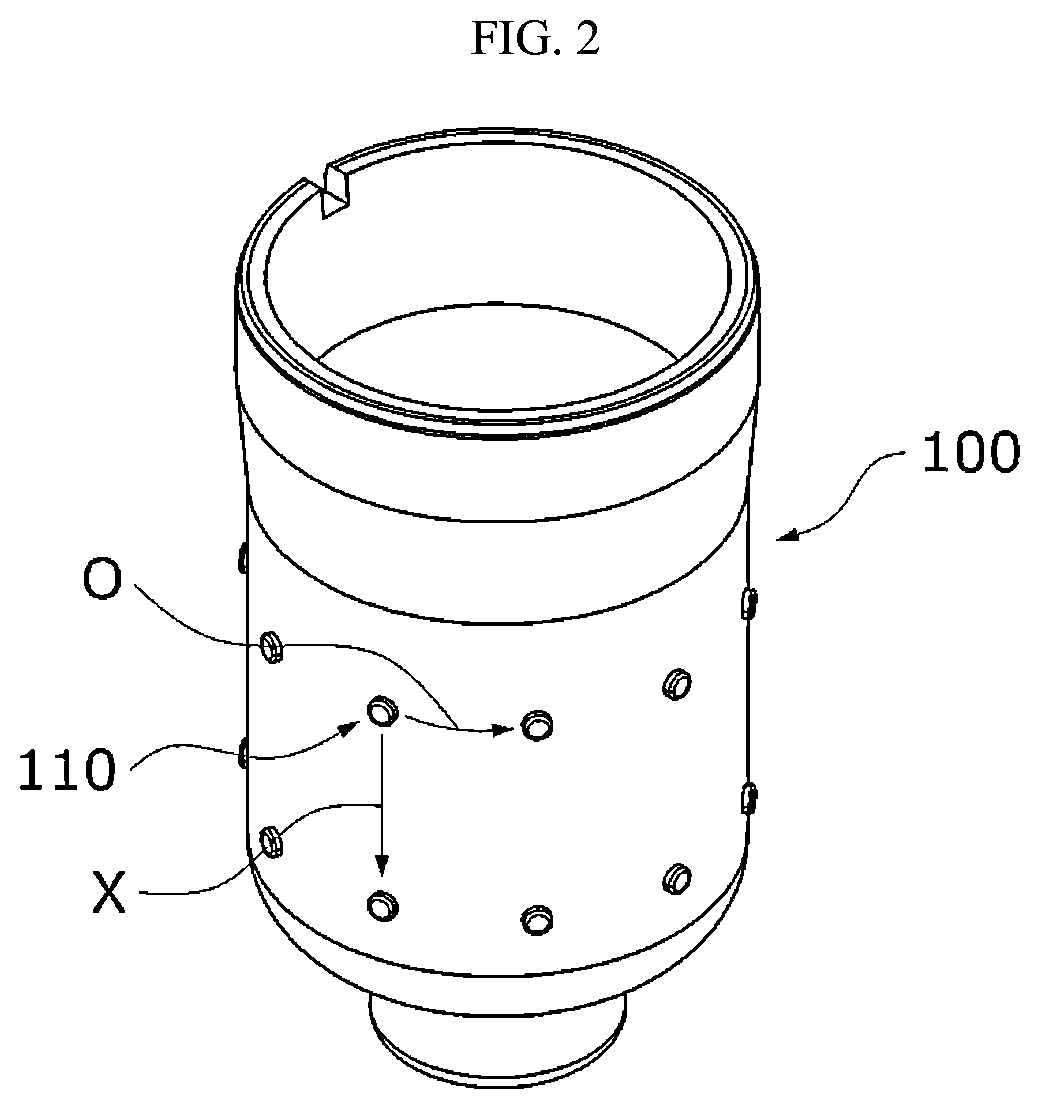
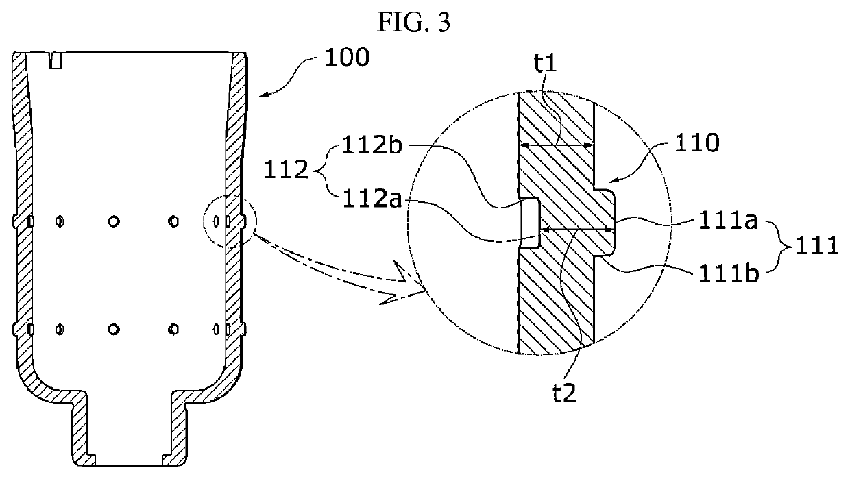
The present invention may provide a motor including a stator, a shaft having a hollow and disposed inside the stator, and a magnet disposed on an outer circumferential surface of the shaft, wherein the shaft includes protrusions in contact with the magnet, and the protrusions include first faces protruding from the outer circumferential surface of the shaft and second faces concavely disposed in an inner circumferential surface of the shaft.

Description

TECHNICAL FIELD[0001]The present invention relates to a motor.BACKGROUND ART[0002]Motors are apparatuses configured to convert electrical energy to mechanical energy to obtain rotational forces and are widely used for vehicles, home appliances, industrial machines, and the like.[0003]Particularly, an electronic power steering (EPS) system in which the motor is used secures turning stability and provides a rapid restoring force by driving the motor according to traveling conditions using an electronic control unit (ECU). Accordingly, a driver of a vehicle can drive safely.[0004]A motor includes a shaft and a stator. The shaft may have a hollow shape. Magnets may be attached to an outer circumferential surface of the shaft. In this case, the hollow shaft has a problem of difficulty in aligning positions of the magnets. This is because it is difficult to form guides for aligning the magnets due to a process of machining the hollow shaft. When there are no guides, which guide the magnet...

Claims


Application Information

Patent Timeline
IPC IPC(8): H02K7/00H02K1/278H02K1/28
CPCH02K7/003H02K1/28H02K1/278H02K1/274H02K1/12H02K1/185H02K5/04
Inventor JO, JUNG WOOKIM, JIN HO
Owner LG INNOTEK CO LTD
Learn More