
Storage Device

Pending Publication Date: 2022-07-28
MOTLEY II RANDOLPH
View PDF44 Cites 0 Cited by
  • Summary
  • Abstract
  • Description
  • Claims
  • Application Information

AI Technical Summary

Benefits of technology

The present invention relates to a gear storage kit that includes a storage box and a companion smartphone application, which allows for remote control of the electric motor which controls the movement and security of the gear stored inside the box. The storage box is designed to be mounted on ceiling joists or studs and includes a base with retention grooves and a plastic outer shell to protect gear from moisture. The storage frame is designed to securely store fishing rods and other elongated items, keeping them organized, safe, and accessible while keeping them out of harmful environments. The invention allows for easy access to gear while still protecting it from theft or damage. Overall, the gear storage kit and frame provide a convenient and secure way to store and protect gear.

Problems solved by technology

However, fishing lines can quickly become entangled if not handled properly, thereby causing problems while using and storing fishing equipment.
Further, in between fishing trips, or during the off season, it can be difficult to find a proper storage location for one's fishing gear.
Keeping rods in a shed, garage, or damp basement can lead to damaged rods, lines becoming entangled, and reels becoming rusted, all of which are frustrating and costly.
Due to poorly chosen storage spaces, fishing poles can break and reels can become contaminated and rusted, thereby leaving the fishing gear damaged and unusable.
Additionally, when fishing rods and other similar fishing gear, are stored in a truck, garage, or other improper location, which is easily accessible and visible to others, there is always the risk of theft causing the user to absorb the financial loss of their fishing gear.
Stolen gear also causes inconvenience to the users and increases the general expenses associated with the sport of fishing.

Method used


Image

  • Storage Device
  • Storage Device
  • Storage Device

Examples


Embodiment Construction

[0028]The innovation is now described with reference to the drawings, wherein like reference numerals are used to refer to like elements throughout. In the following description, for purposes of explanation, numerous specific details are set forth in order to provide a thorough understanding thereof. It may be evident, however, that the innovation can be practiced without these specific details. In other instances, well-known structures and devices are shown in block diagram form in order to facilitate a description thereof. Various embodiments are discussed hereinafter. It should be noted that the figures are described only to facilitate the description of the embodiments. They are not intended as an exhaustive description of the invention and do not limit the scope of the invention. Additionally, an illustrated embodiment need not have all the aspects or advantages shown. Thus, in other embodiments, any of the features described herein from different embodiments can be combined.

[0...


PUM


Abstract

This present invention relates to a ceiling mounted gear storage unit for storing and protecting gear, for example, fishing rods and reels. The storage unit includes an inconspicuous frame having a base with a plurality of retention grooves, carabiners, or bands; and, a cable and pulley system or electric motor and gear system to raise or lower the gear storage unit. The storage unit can be controlled using a remote application or other transmitter to operate the storage unit. An electronic lock mechanism can include an access code for providing access to the storage unit. The storage unit can be mounted to a ceiling joist(s) using wood screws.

Description

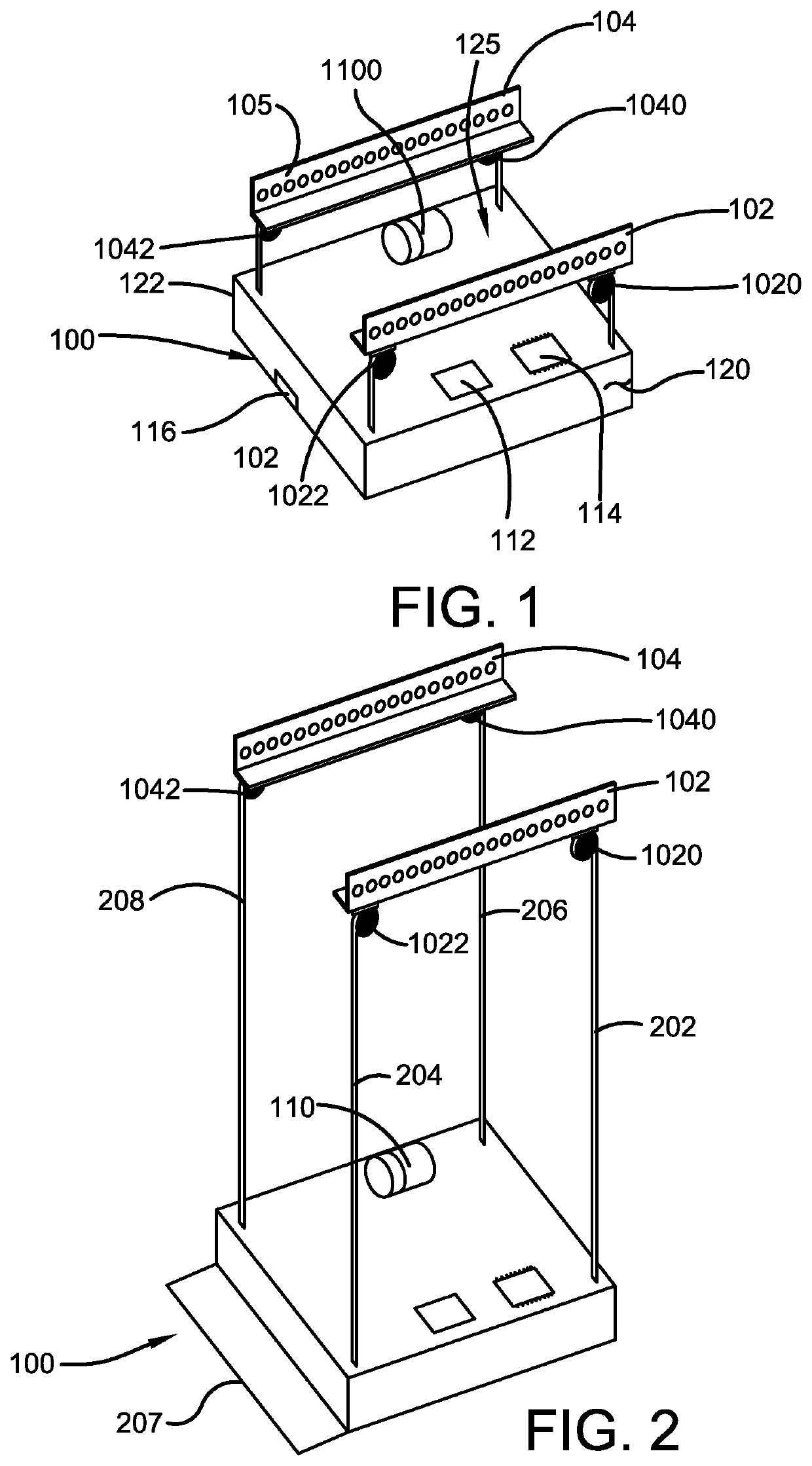
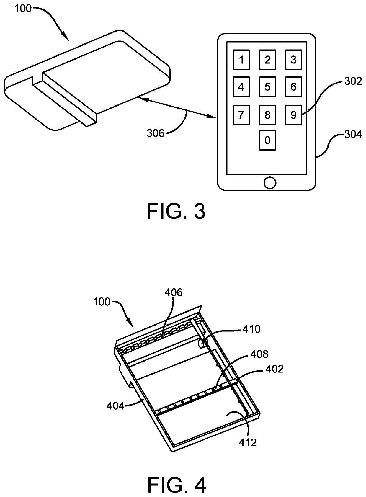
CROSS-REFERENCE TO RELATED APPLICATION[0001]The present application claims priority to, and the benefit of, U.S. patent application Ser. No. 17 / 242,994, which was filed on Apr. 28, 2021, which claims priority to, and the benefit of, U.S. patent application Ser. No. 17 / 234,880, which was filed on Apr. 20, 2021 and claims priority from U.S. Provisional Application No. 63 / 012,990, which was filed on Apr. 21, 2020 and is incorporated herein by reference in its entirety.FIELD OF THE INVENTION[0002]The present invention relates generally to the field of storage devices. More specifically, the present invention relates to a locked or hinged storage unit for storing valuables in an inconspicuous, secretive, and dry manner. The storage device, to be described in detail hereinafter, provides for an undetectable or out of reach storage compartment. Items to be stored vary and can include any valuables or items such as fishing rods and reels, jewelry, firearms, photographs, etc. The storage dev...

Claims


Application Information

Patent Timeline
IPC IPC(8): A47B46/00A47B81/00
CPCA47B46/005A47B2051/005A47B81/005A47F7/0021H04M1/72412A47B51/00A47F7/0035A47B2220/0097
Inventor MOTLEY, II, RANDOLPH
Owner MOTLEY II RANDOLPH
Learn More