Robotically-driven surgical instrument with e-beam driver

a robotic and surgical instrument technology, applied in the field of surgical instruments, can solve the problems of complicated approaches to articulating surgical stapling and severing instruments, and achieve the effects of reducing cross sectional area and the ability to flex, enhancing use in articulating surgical instruments, and ensuring the accuracy of articulation

Pending Publication Date: 2022-07-28
CILAG GMBH INT
View PDF8 Cites 98 Cited by
  • Summary
  • Abstract
  • Description
  • Claims
  • Application Information

AI Technical Summary

Benefits of technology

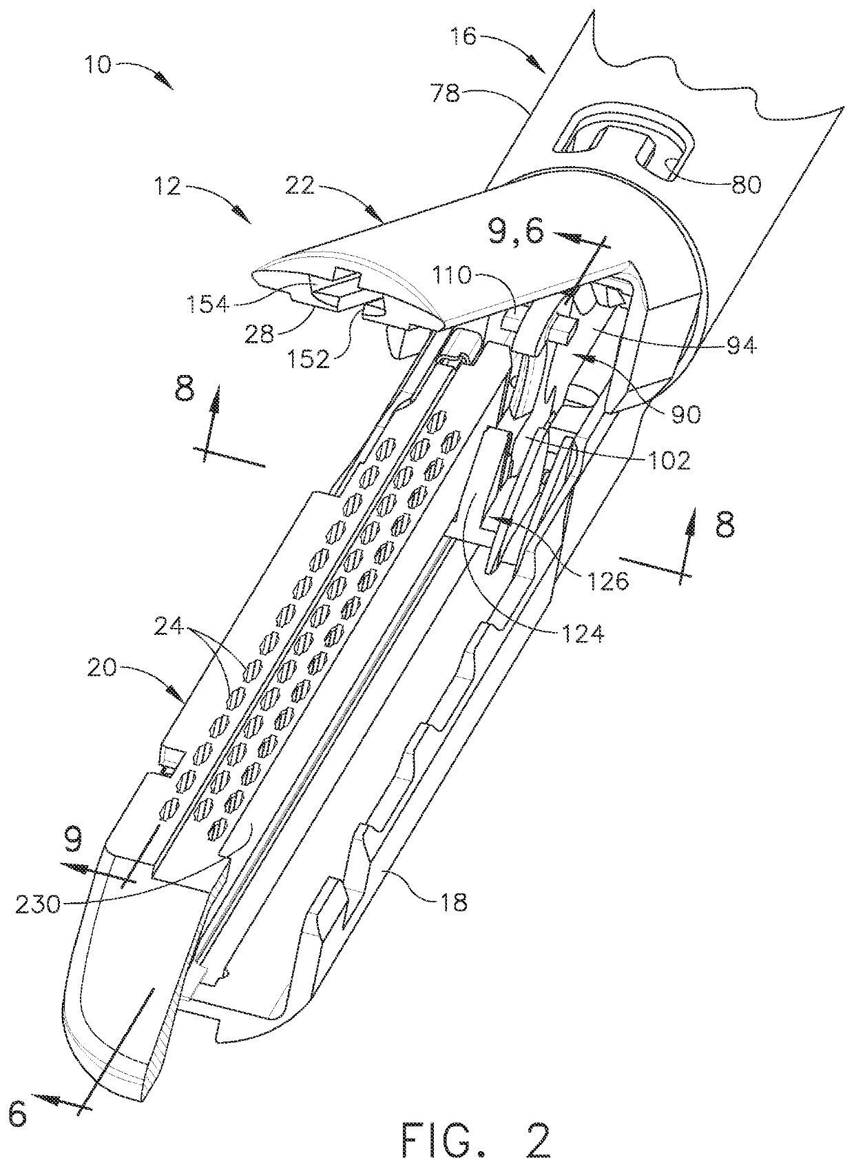
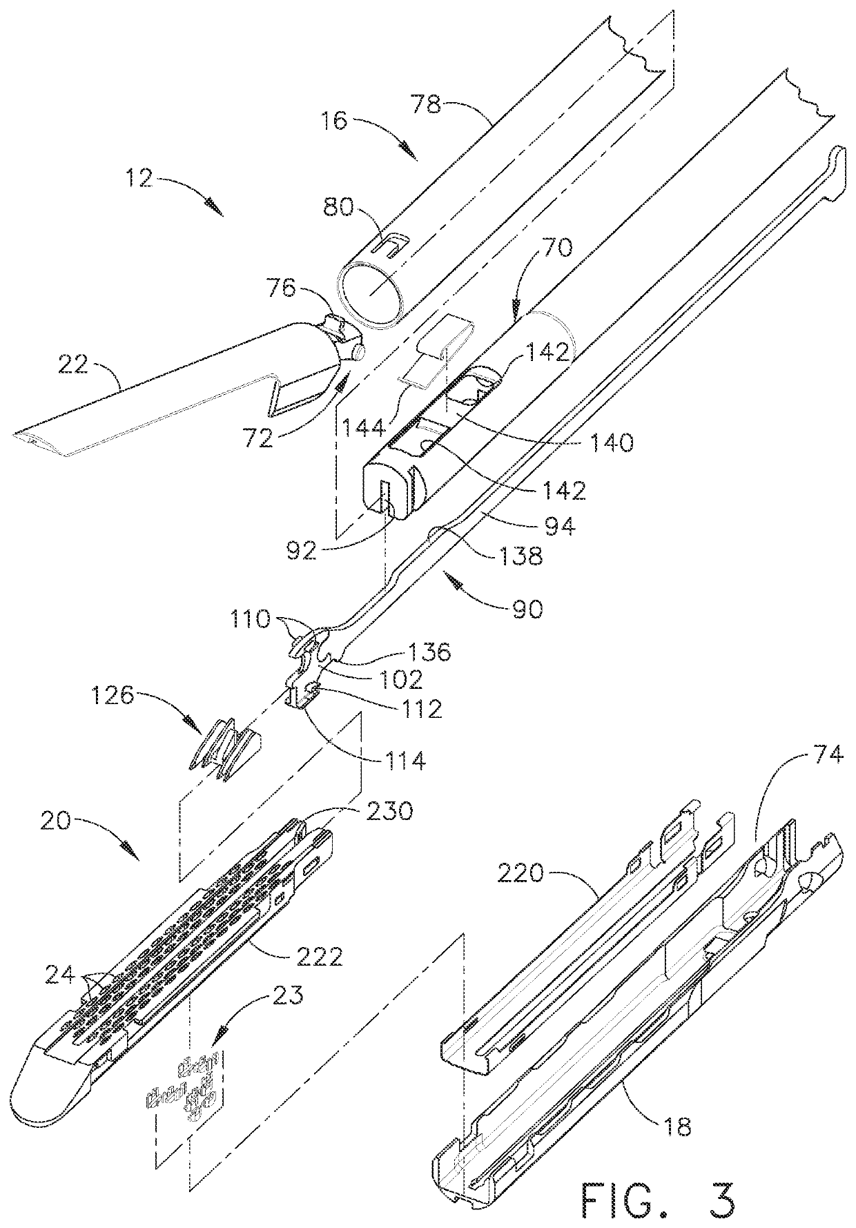
[0012]The invention overcomes the above-noted and other deficiencies of the prior art by providing a firing mechanism that affirmatively vertically spaces an end effector of a surgical stapling and severing instrument. Thus, the instrument structurally assures adequate spacing to achieve proper stapling, even in instances where too little tissue is clamped in the end effector. Integrally forming these features into an E-beam that includes a cutting edge realizes consistent spacing and performance as the E-beam fires through an end effector such as a severing and stapling assembly. Further, proximally attaching a separate, thinned firing bar to the E-beam enhances use in articulating surgical instruments wherein reduced cross sectional area and the ability to flex in a plane of articulation are desirable.
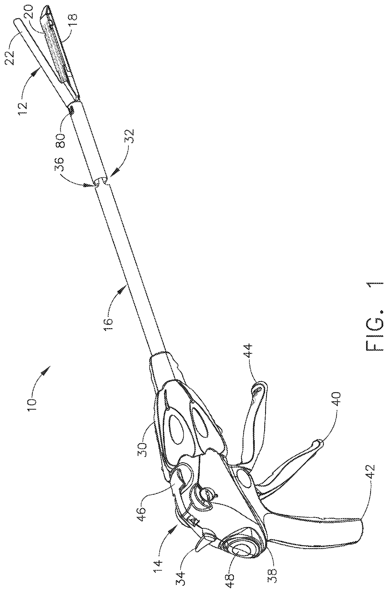
[0013]In one aspect of the invention, a surgical instrument includes a handle portion operable to produce a firing motion that actuates an implement portion. This implement portion has an elongate channel that receives a staple cartridge opposed by a pivotally attached anvil. A firing device includes a distally presented cutting edge longitudinally received between the elongate channel and the anvil, an upper member engageable to the anvil channel, a lower member engaging the channel slot, and a middle member operable to actuate the wedge sled, which is integral to the staple cartridge. The middle member advantageously opposes pinching of the end effector, assuring proper staple formation even when an otherwise too small amount of tissue has been clamped. These spacing and cutting features are advantageously formed into an E-beam while flexibility for articulation is provided by a thinned firing bar attached to the E-beam.

Problems solved by technology

Approaches to articulating a surgical stapling and severing instrument tend to be complicated by integrating control of the articulation along with the control of closing the end effector to clamp tissue and fire the end effector (i.e., stapling and severing) within the small diameter constraints of an endoscopic instrument.

Method used


Image

  • Robotically-driven surgical instrument with e-beam driver
  • Robotically-driven surgical instrument with e-beam driver
  • Robotically-driven surgical instrument with e-beam driver

Examples


Embodiment Construction

[0152]Applicant of the present application also owns the following patent applications which were filed on May 27, 2011 and which are each herein incorporated by reference in their respective entireties:

[0153]U.S. patent application Ser. No. 13 / 118,259, entitled SURGICAL INSTRUMENT WITH WIRELESS COMMUNICATION BETWEEN A CONTROL UNIT OF A ROBOTIC TOOL SYSTEM AND REMOTE SENSOR, now U.S. Pat. No. 8,684,253;

[0154]U.S. patent application Ser. No. 13 / 118,210, entitled ROBOTICALLY-CONTROLLED DISPOSABLE MOTOR DRIVEN LOADING UNIT, now U.S. Pat. No. 8,752,749;

[0155]U.S. patent application Ser. No. 13 / 118,194, entitled ROBOTICALLY-CONTROLLED ENDOSCOPIC ACCESSORY CHANNEL, now U.S. Pat. No. 8,992,422;

[0156]U. S. patent application Ser. No. 13 / 118,253, entitled ROBOTICALLY-CONTROLLED MOTORIZED SURGICAL INSTRUMENT, now U.S. Pat. No. 9,386,983;

[0157]U.S. patent application Ser. No. 13 / 118,278, entitled ROBOTICALLY-CONTROLLED SURGICAL STAPLING DEVICES THAT PRODUCE FORMED STAPLES HAVING DIFFERENT LENG...


PUM


Abstract

A surgical severing and stapling instrument, suitable for laparoscopic and endoscopic clinical procedures, clamps tissue within an end effector of an elongate channel pivotally opposed by an anvil. Various embodiments are configured to be operably attached to a robotic system to receive actuation / control motions therefrom.

Description

CROSS REFERENCE TO RELATED APPLICATIONS[0001]This application is a continuation application claiming priority under 35 U.S.C. § 120 to U.S. patent application Ser. No. 17 / 244,022, entitled ROBOTICALLY-DRIVEN SURGICAL INSTRUMENT WITH E-BEAM DRIVER, filed Apr. 29, 2021, now U.S. Patent Application Publication No. 2021 / 0315577, which is a continuation application claiming priority under 35 U.S.C. § 120 to U.S. patent application Ser. No. 16 / 420,522, entitled ROBOTICALLY-DRIVEN SURGICAL INSTRUMENT WITH E-BEAM DRIVER, filed May 23, 2019, now U.S. Patent Application Publication No. 2019 / 0343525, which is a continuation application claiming priority under 35 U.S.C. § 120 to U.S. patent application Ser. No. 14 / 867,362, entitled SURGICAL INSTRUMENTS WITH E-BEAM DRIVER AND ROTARY DRIVE ARRANGEMENTS, filed Sep. 28, 2015, which issued on Jul. 9, 2019 as U.S. Pat. No. 10,342,541, which is a continuation application claiming priority under 35 U.S.C. § 120 to U.S. patent application Ser. No. 14 / 74...

Claims


Application Information

Patent Timeline
Patent Type & Authority Applications(United States)
IPC IPC(8): A61B17/10A61B34/30A61B50/20A61B17/072A61B17/068A61B17/064
CPCA61B17/105A61B34/30A61B50/20A61B17/07207A61B34/37A61B17/0682A61B17/068A61B17/064A61B17/072A61B17/320092A61B18/1445A61B2017/00017A61B2017/00398A61B2017/00734A61B2017/07271A61B2017/07278A61B2017/07285A61B2017/2927A61B2018/00607A61B2018/0063A61B2018/1455A61B2090/0807A61B50/36A61B2017/00473A61B2017/0688A61B2017/320094A61B2090/0805A61B2034/306A61B2017/320093A61B2017/320095A61B2017/320097A61B2034/302A61B2017/2923A61B2017/320052A61B2017/07257
Inventor SHELTON, IV, FREDERICK E.SETSER, MICHAEL E.WEISENBURGH, II, WILLIAM B.
Owner CILAG GMBH INT
Why Eureka
Try Eureka