Repositionable medical tube with ultrasonically-detectable cuff

a medical tube and ultrasonically-detectable technology, applied in the field of repositionable medical tubes, can solve the problems of increased risk of complications in critically ill pediatric patients, increased cost of chest x-rays for the primary purpose of checking the position of the ett, and increased risk of neurologic injury and death

Pending Publication Date: 2022-07-28
RGT UNIV OF MICHIGAN
View PDF0 Cites 0 Cited by
  • Summary
  • Abstract
  • Description
  • Claims
  • Application Information

AI Technical Summary

Benefits of technology

[0006]A repositionable medical tube of the present disclosure, which may be in the form of an endotracheal tube (ETT), a nasal airway tube such as a nasogastric tube, or a nasojejunal tube, for example, includes at least one inflatable cuff having a geometric topography that facilitates detection by ultrasound to confirm the position of the medical tube. An ultrasonic transducer can be operated to transmit signals intended for use in detecting the presence (or absence) of foreign objects at specific depths under the skin of a patient. This ability to focus ultrasonic energy to a specific depth provides an opportunity to discern specific objects within the patient while mitigating the risk of confusion of the medical tube with other lumens at different depths under the skin of the patient.

Problems solved by technology

Subsequently, mechanically ventilated neonatal and pediatric ICU patients undergo frequent (sometimes daily) chest x-rays to confirm ETT position due to the serious and potentially life-threatening consequences of unplanned / unrecognized extubations and malpositioned ETTs.
Incorrect ETT placement can result in vocal cord injury, barotrauma, hypoxia, neurologic injury, and death.
Critically ill pediatric patients are at increased risk for these complications due, in part, to their higher oxygen consumption rates than adults.
Chest x-rays for the primary purpose of checking ETT position are costly, logistically burdensome, difficult to interpret, and an increased health risk (due to life-time cumulative radiation exposure and late cancers, particularly in children).
Among the factors that complicate interpretation of chest x-rays when attempting to verify ETT location, particularly in neonatal and pediatric patients, is the presence of a plurality of lumens, wires, cuffs, bandages, gauze, medical tape, and other paraphernalia that, particularly in a two-dimensional image such as an x-ray, renders the ETT, and components thereof, virtually indistinguishable from one or more of those other objects.

Method used


Image

  • Repositionable medical tube with ultrasonically-detectable cuff
  • Repositionable medical tube with ultrasonically-detectable cuff
  • Repositionable medical tube with ultrasonically-detectable cuff

Examples


third embodiment

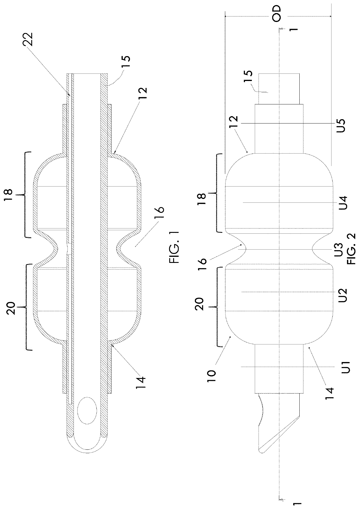
[0050]While the cuff has been illustrated as having a single divot, an alternate embodiment is for the cuff to be provided with multiple divots, such as illustrated in FIGS. 10 and 11. According to this third embodiment, the cuff 10 includes a proximate cuff region 18, a distal cuff region 20, a central cuff region 24, a first, proximal divot region 16A, disposed between the central cuff region 24 and the proximate cuff region 18, and a second, distal divot region 16B, disposed between the central cuff region 24 and the distal cuff region 20. The proximate cuff region 18, the distal cuff region 20, the central cuff region 24, the first, proximal divot region 16A, and the second, distal divot region 16B are in fluid communication with one another and share a common single inflation lumen 22.

fourth embodiment

[0051]A fourth embodiment is illustrated in FIGS. 12 and 13. According to this embodiment, the proximate cuff region 18 and the distal cuff region 20 are not in fluid communication with one another. Instead, the proximate cuff region 18 may be selectively inflated and deflated via a proximate cuff inflation lumen 22A with which the proximate cuff region 18 is in fluid communication, and the distal cuff region 20 may be selectively inflated and deflated via a distal cuff inflation lumen 22B with which the distal cuff region 20 is in fluid communication. The distal cuff inflation lumen 22B is fluidly isolated from the proximate cuff inflation lumen 22A. Both the proximate cuff inflation lumen 22A and the distal cuff inflation lumen 22B may be substantially coextensive with the primary lumen 15 of the medical tube, and preferably incorporated into the wall of the primary lumen 15. According to this embodiment, the divot region 16 is defined between the proximate cuff region 18 and the ...

fifth embodiment

[0052]the present disclosure is illustrated in FIGS. 14-16. According to this embodiment, a pair of axially extending divot regions 116 are provided, each of which is axially coextensive with first and second cuff regions 126, 128. A benefit of such one or more axially extending divot regions 116 is that the divot region 116 can be used in concert with an ultrasound probe to detect rotation of the medical tube, which can be useful in guiding or verifying proper advancement as between the trachea versus the esophagus. Rotation of an ultrasound probe through an angle of, for example, about 90° can permit depth readings with the ultrasound probe that would not be achievable using a medical tube lacking such axially-extending divot regions 116. While the first and second cuff regions 126, 128 could both be inflated with the same fluid, it may be desirable to fill the first cuff region 126 with a different fluid than the second cuff region 128, such as filling one of the cuff regions wit...


PUM


Abstract

A repositionable medical tube, such as an endotracheal tube, a nasogastric tube, or a nasojejunal tube, having an inflatable cuff with at least one divot region therein, the divot region having an outer diameter sufficiently smaller than an outer diameter of both a proximate cuff region and of a distal cuff region as to produce a discernibly-distinct ultrasonic image when scanned by an ultrasound sensor. The medical tube may be further provided with an ultrasonically-detectable coil or one or more ultrasonically-detectable markers having an identifiable geometric shape when the marker is visible using an ultrasonic probe.

Description

CROSS-REFERENCE TO RELATED APPLICATIONS[0001]This application claims priority to, and the benefit of the filing date of, U.S. Provisional Application No. 62 / 859,518, filed Jun. 10, 2019, which is hereby incorporated by reference in its entirety.STATEMENT OF FEDERALLY SPONSORED RESEARCH AND DEVELOPMENT[0002]This invention was made with government support under Contract No. FD-003787 awarded by the US Food and Drug Administration. The government has certain rights in the invention.FIELD OF THE DISCLOSURE[0003]This disclosure relates generally to repositionable medical tubes, such as endotracheal tubes (ETTs) and, more specifically, to medical tubes having one or more inflatable cuffs with geometric features to promote ultrasonic detection and facilitate verification of the tube's location, e.g. in the case of an ETT, tracheal versus esophageal position and depth relative to vocal cords and carina, without need for chest radiography.DESCRIPTION OF THE PRIOR ART[0004]Currently, there ar...

Claims


Application Information

Patent Timeline
Patent Type & Authority Applications(United States)
IPC IPC(8): A61M25/01A61M16/04A61J15/00
CPCA61M25/0108A61M16/0445A61J15/0003A61M25/1002A61M16/0438A61M16/0459A61J15/0049A61B8/0841A61M2205/3375A61M16/0411A61M2240/00A61M16/0486A61M16/0454A61M16/0425A61M2205/32A61M25/1011
Inventor CHARPIE, JOHNHARRIS, ADRIENNE R.SMITH, SHEPHERDMCARTHUR, KEGANPARUNAK, GENE
Owner RGT UNIV OF MICHIGAN
Why Eureka
Try Eureka