
Lamp bead support with opening between electrical contacts and light fixture having the same

a technology of electrical contacts and lamp bead supports, which is applied in the direction of light fastenings, solid-state devices, lighting and heating apparatus, etc., can solve the problem of not being able to snip copper wires between signal inputs

Active Publication Date: 2022-07-28
CHONGYI JINGYI LIGHTING PROD CO LTD
View PDF1 Cites 0 Cited by
  • Summary
  • Abstract
  • Description
  • Claims
  • Application Information

AI Technical Summary

Benefits of technology

The patent describes a device that makes it easier to cut signal wires between input and output, which are commonly used for lighting. This makes it simpler to create light strings.

Problems solved by technology

However, when wire rod snipping process is performed on existing lamp bead supports, it has following disadvantages: it is not convenient to snip the copper wire between the signal input and signal output.

Method used


Image

  • Lamp bead support with opening between electrical contacts and light fixture having the same
  • Lamp bead support with opening between electrical contacts and light fixture having the same
  • Lamp bead support with opening between electrical contacts and light fixture having the same

Examples


Embodiment Construction

[0046]In order to clarify the purpose, technical solutions and advantages of embodiments of the present application, the technical solutions in the embodiments of this application will be described clearly and completely below in combination with the drawings in the embodiments of this application. Evidently, the described embodiments are a part of the embodiments of this application instead of the entire embodiments. Typically, the components of the embodiments of this application described and shown in the drawings herein can be arranged and designed in various different configurations.

[0047]In description of this application, it should be noted that the orientation or positional relations indicated by terms such as “in” and “out” are orientation or positional relations based on the drawings, or orientation or positional relations in which the product of this application is conventionally placed in use, which merely intends to facilitate the description of this application and to ...


PUM


Abstract

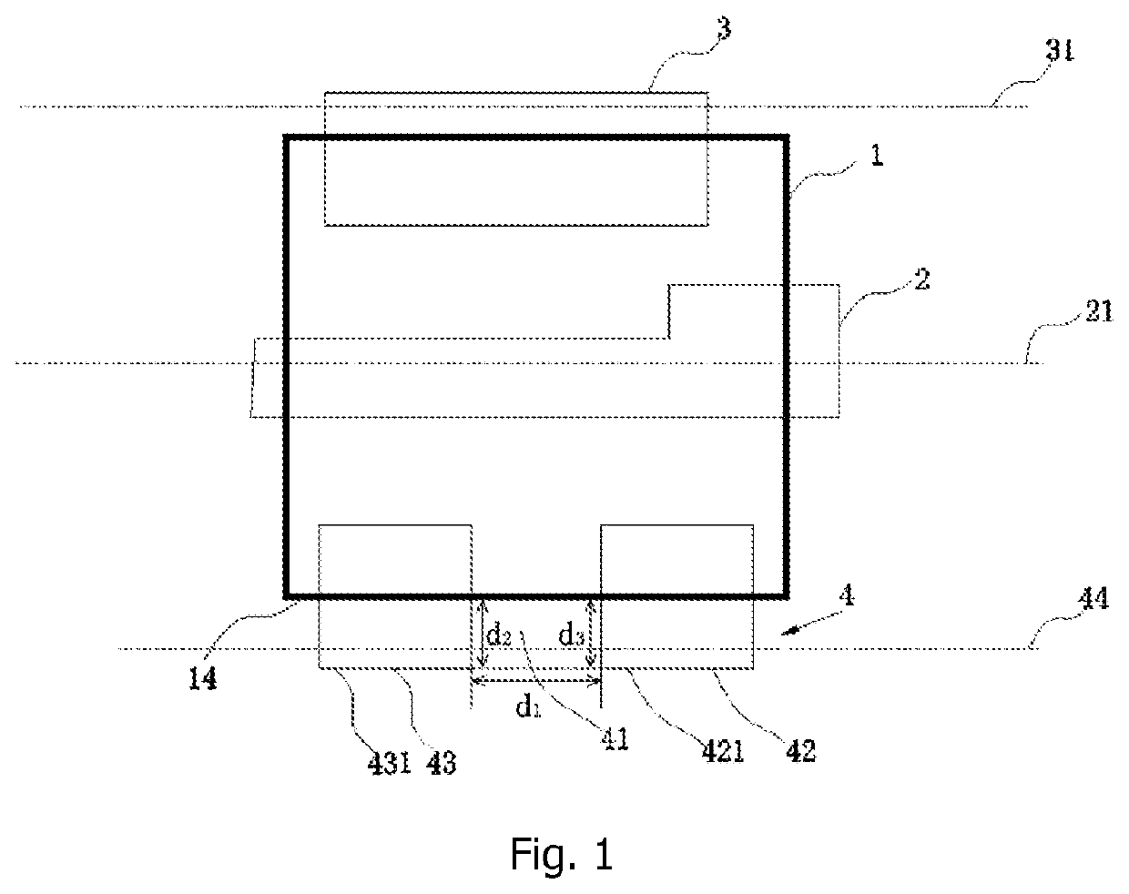
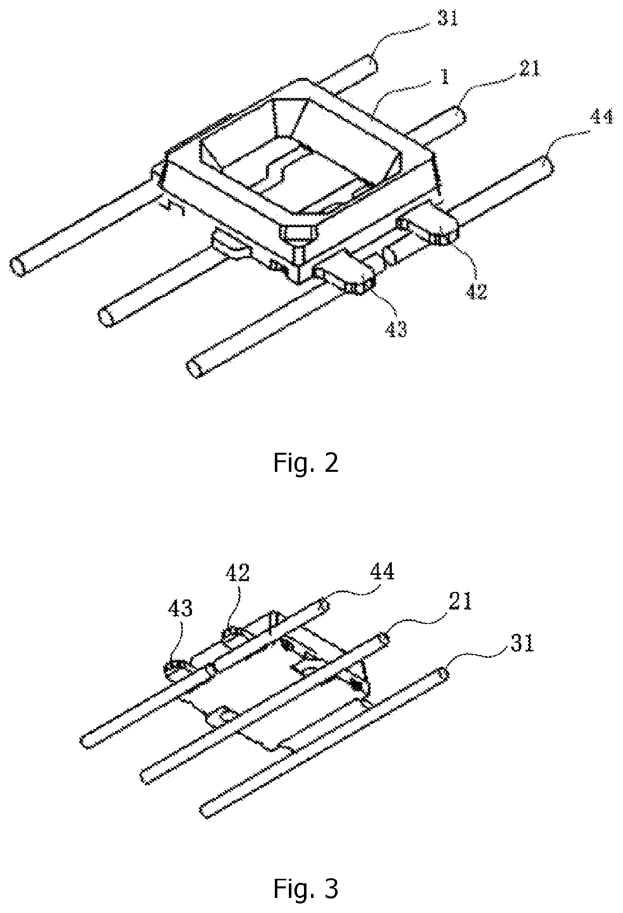
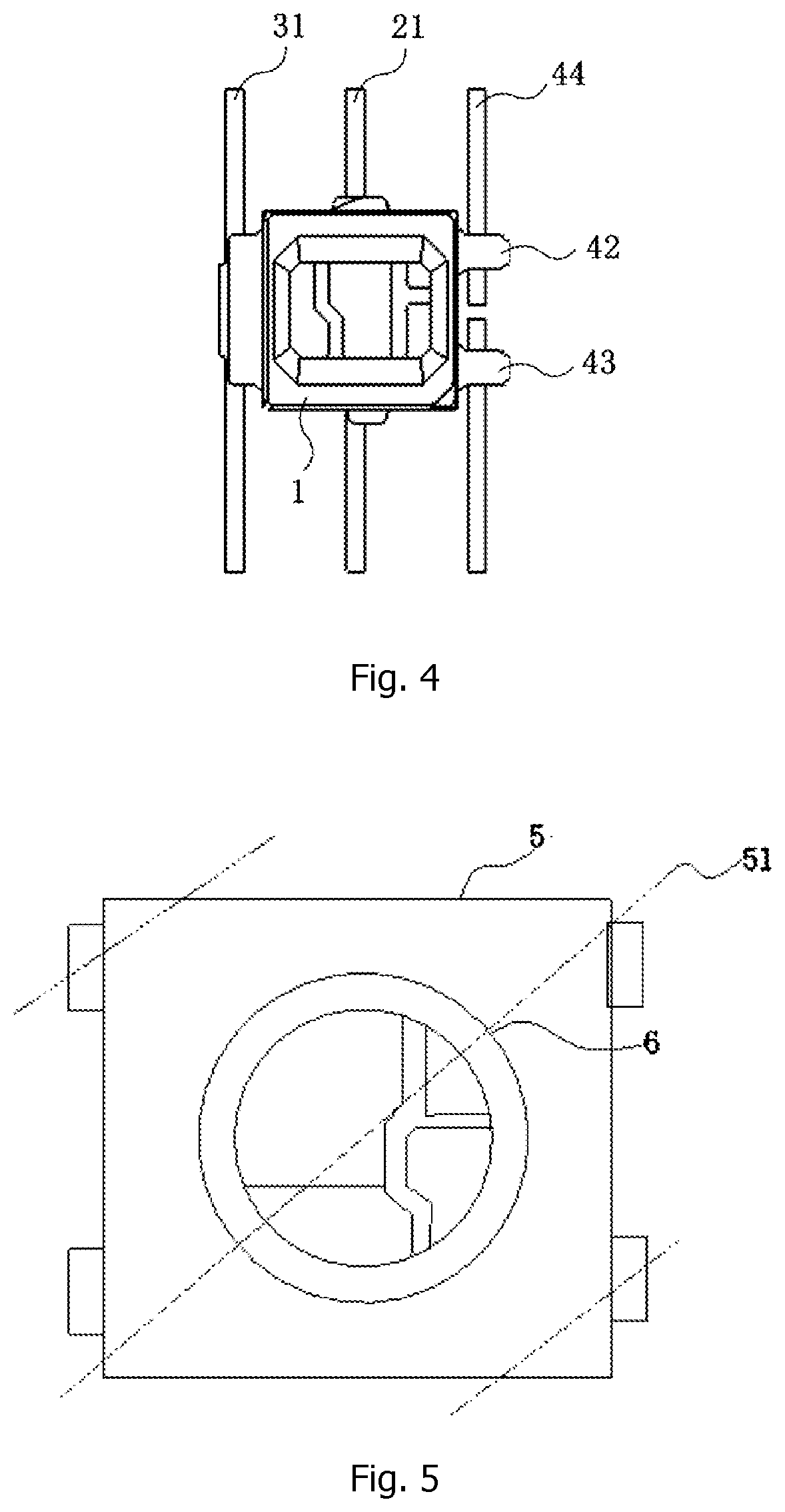
The present application relates to a lamp bead support and a light fixture, wherein the lamp bead support comprises a frame body and a first circuit board which is connected with the frame body; the first circuit board comprises a first weld portion and a second weld portion which extend out of the frame body; and the first weld portion and the second weld portion form a snipping opening at the outside of the frame body.

Description

CROSS-REFERENCES TO RELATED APPLICATIONS[0001]This application claims the benefit of the Chinese Patent Application 202110097609.5, entitled “Lamp bead support and light fixture”, and filed on Jan. 25, 2021, the entire contents of which are incorporated herein by reference.TECHNICAL FIELD[0002]The present application relates to the technical field of illuminative decoration, and specifically to a lamp bead support and a light fixture.BACKGROUND ART[0003]Typically, there are 4 welding pins at the bottom of a point-control lamp bead support, including an anode, a cathode, a signal input, a signal output, wherein in order that the lamp beads can work properly, there shall be no connection between the signal input and signal output, thus the two must be spaced apart and the wire rod shall be snipped.[0004]However, when wire rod snipping process is performed on existing lamp bead supports, it has following disadvantages: it is not convenient to snip the copper wire between the signal inp...

Claims


Application Information

Patent Timeline
IPC IPC(8): F21V19/00F21V23/00
CPCF21V19/0025F21V23/002F21V23/00H01L33/62H01L25/13F21S4/10
Inventor HE, YAOQUAN
Owner CHONGYI JINGYI LIGHTING PROD CO LTD
Learn More