External vascular compression device for use during cardiac arrest

a compression device and cardiac arrest technology, applied in the field of external vascular compression devices for cardiac arrest, can solve the problems of morbidity and mortality, and achieve the effects of enhancing blood supply to vital organs, reducing friction, and reducing mortality

Pending Publication Date: 2022-08-04
THE MEDICAL UNIV OF SOUTH CAROLINA
View PDF0 Cites 1 Cited by
  • Summary
  • Abstract
  • Description
  • Claims
  • Application Information

AI Technical Summary

Problems solved by technology

Morbidity and mortality occur because of the limited blood supply to the vital organs such as the brain and heart.

Method used


Image

  • External vascular compression device for use during cardiac arrest
  • External vascular compression device for use during cardiac arrest
  • External vascular compression device for use during cardiac arrest

Examples


Embodiment Construction

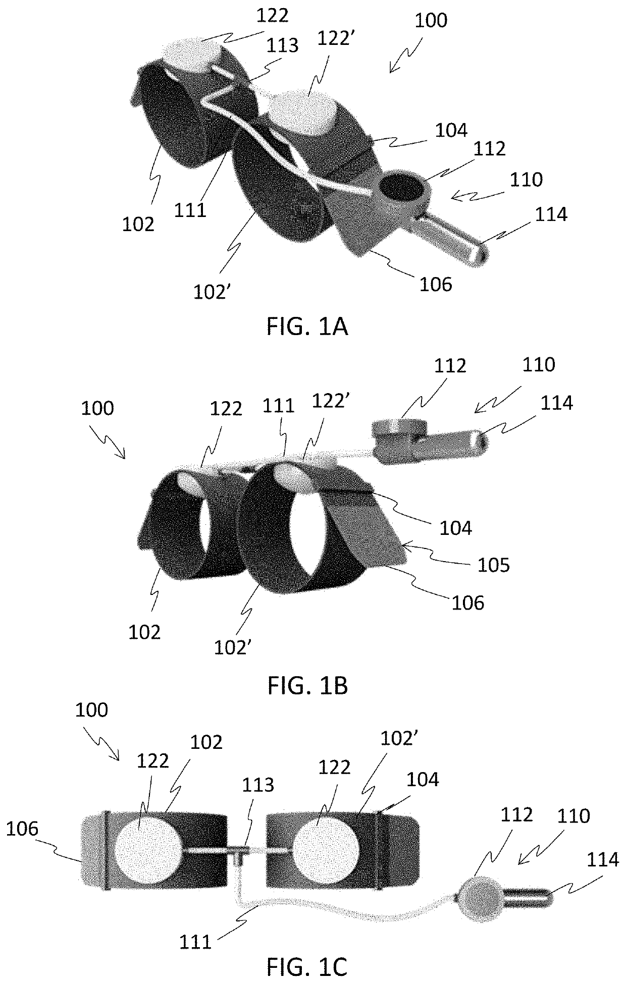
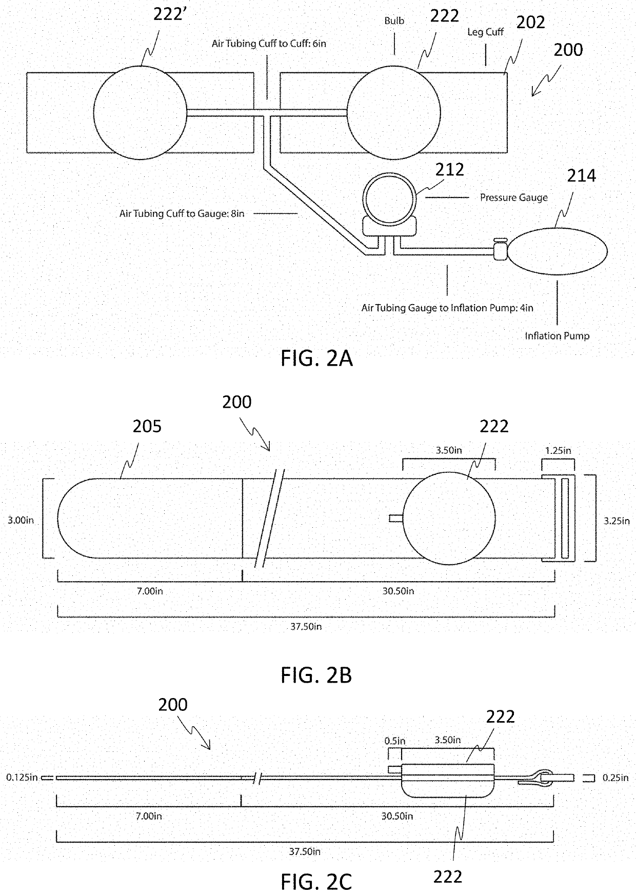
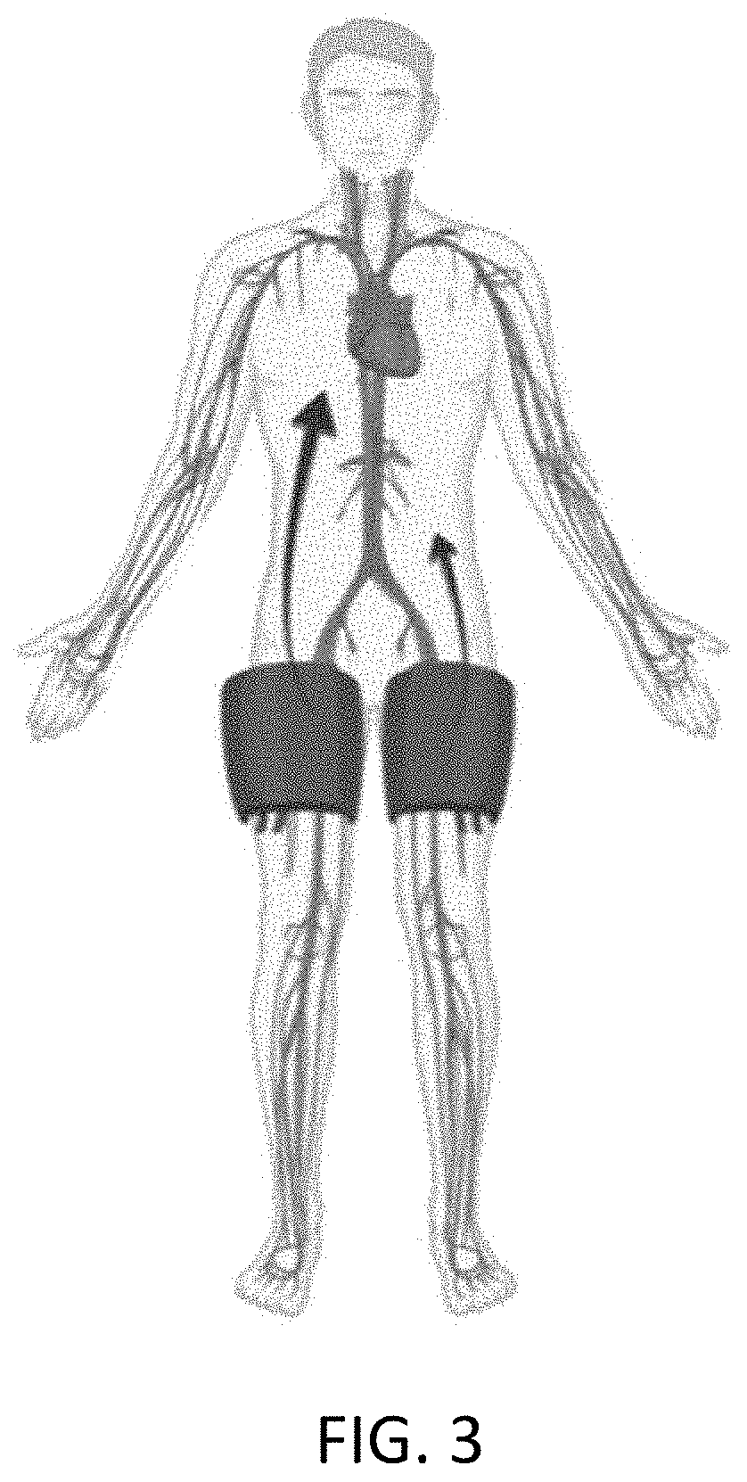
[0013]It is to be understood that the figures and descriptions of the present invention have been simplified to illustrate elements that are relevant for comprehension of the present invention, while eliminating, for the purpose of clarity, many other elements found in vascular compression devices and methods of enhancing blood supply to vital organs. Those of ordinary skill in the art may recognize that other elements and / or steps are desirable and / or required in implementing the present invention. However, because such elements and steps are well known in the art, and because they do not facilitate a better understanding of the present invention, a discussion of such elements and steps is not provided herein. The disclosure herein is directed to all such variations and modifications to such elements and methods known to those skilled in the art.

[0014]Unless defined otherwise, all technical and scientific terms used herein have the same meaning as commonly understood by one of ordi...


PUM


Abstract

A vascular compression device is described. The device includes a first compression loop having a first pneumatic bulb configured to inflate and deflate, a second compression loop having a second pneumatic bulb configured to inflate and deflate, and a pneumatic pump system connected via tubing to the first and second pneumatic bulbs. A method for enhancing blood supply to vital organs is also described.

Description

CROSS-REFERENCE TO RELATED APPLICATIONS[0001]This application claims priority to U.S. provisional application No. 63 / 144,599, filed Feb. 2, 2021, incorporated herein by reference in its entirety.BACKGROUND OF THE INVENTION[0002]Despite decades of medical advancements, cardiopulmonary resuscitation (CPR) has remained largely unchanged since closed chest compressions were described in 1956. Morbidity and mortality remain dismal with only 10.6% of patients who experience cardiac arrest surviving until hospital discharge. Morbidity and mortality occur because of the limited blood supply to the vital organs such as the brain and heart. With closed chest compressions, blood supply is mechanically circulated and pharmacological manipulation of the vascular tree with drugs such as epinephrine and vasopressin are used to augment cardiac contractility and peripheral vasoconstriction. However, blood pressure (BP) can additionally be modulated by mechanical manipulation of the arterial tree (se...

Claims


Application Information

Patent Timeline
Patent Type & Authority Applications(United States)
IPC IPC(8): A61B17/132A61B17/135A61B5/026A61B5/00
CPCA61B17/1325A61B17/1327A61B2017/00544A61B5/026A61B5/7405A61B17/135A61B2017/00199A61B2017/00017A61B2017/00115A61B2562/0247
Inventor QUINN, KRISTENHOLMAN, HEATHERRAJAB, TAUFIEK KONRADPLUMBLEE, LEAHKIM, JOSHUASIEGEL, JULIE
Owner THE MEDICAL UNIV OF SOUTH CAROLINA
Why Eureka
Try Eureka