Apparatus and system for dynamic environmentally actuated ceiling baffle and methods thereof

a technology of dynamic environment and ceiling baffle, which is applied in the direction of instruments, buildings, building components, etc., can solve the problems of no one of these structures or any other, acoustic problems caused by exposed ceilings, and a large amount of noise in the room

Pending Publication Date: 2022-08-04
TURF DESIGN INC
View PDF0 Cites 1 Cited by
  • Summary
  • Abstract
  • Description
  • Claims
  • Application Information

AI Technical Summary

Benefits of technology

[0014]The present disclosure relates to a dynamic environmentally actuated ceiling baffle apparatus and systems, along with the methods for manufacturing, installing and using the dynamic environmentally actuated ceiling baffles. In particular, the present disclosure relates to dynamic environmentally actuated ceiling baffles and systems that incorporate inputs from the system or users based on the environment, including room acoustics, to properly configure and reconfigure the dynamic environmentally actuated ceiling baffle to counter or respond to the environment, including to reduce unwanted noise.
[0018]The present disclosure contemplates that each of the above-referenced dynamic environmentally actuated ceiling baffles can be quickly and easily installed onto construction ceiling hangers and other ceiling structures, using integrated locks, cables or magnets, to produce a manual, automatic or programmable dynamic environmentally actuated baffle system, and to provide an aesthetically pleasing image, along with a reduction in unwanted noise and / or room acoustics.
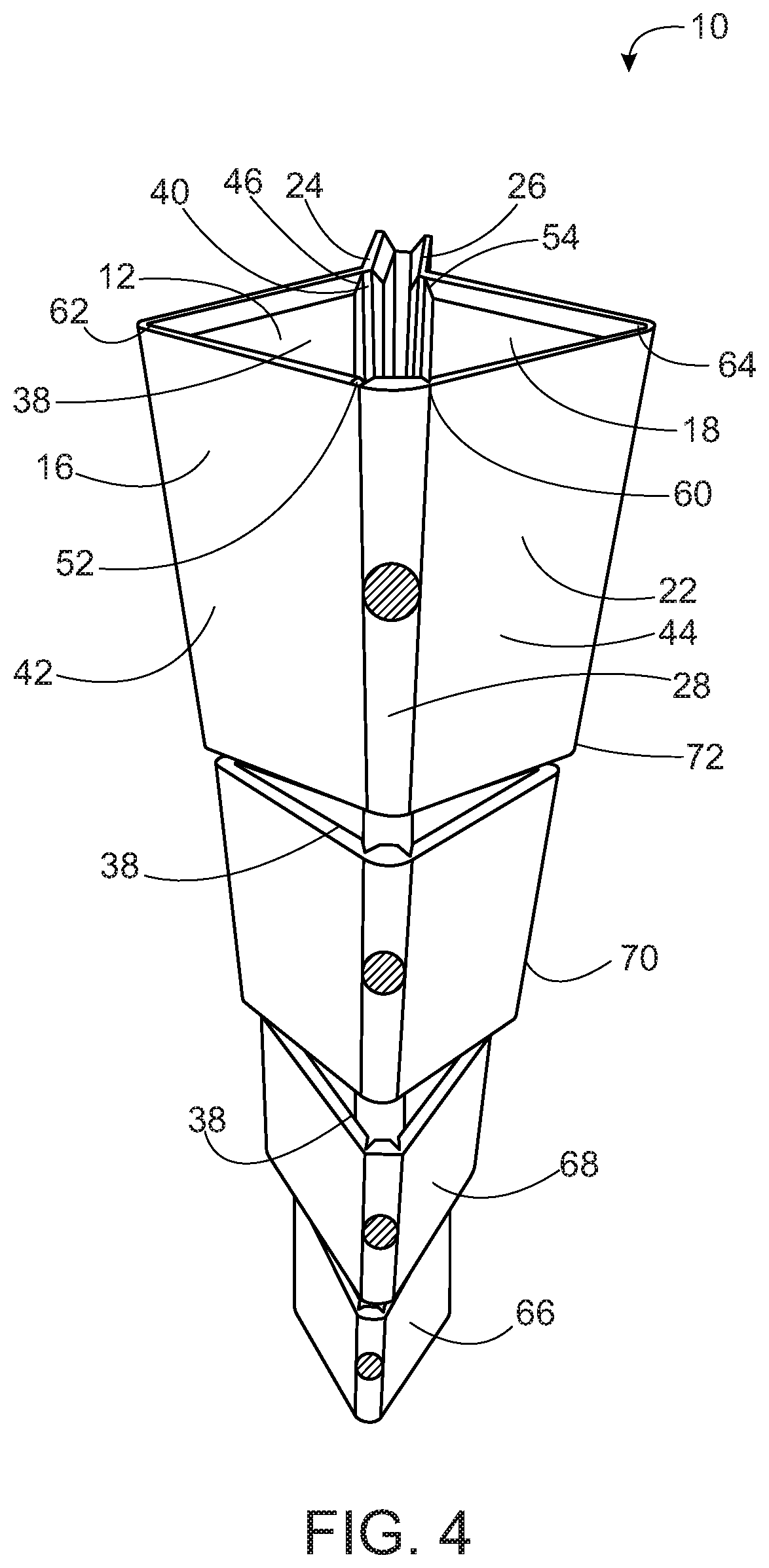
[0021]The present disclosure is an improved dynamic environmentally actuated ceiling baffle that utilizes kerfs or cuts in the sidewall, top and bottom portions to facilitate the configuring and reconfiguring of the ceiling baffle into the optimal shape to respond to the environment, including for reduction in unwanted noise and / or unwanted room acoustics. The optimal shape of the dynamic environmentally actuated ceiling baffle, from fully expanded (largest air gap) to fully collapsed (smallest or no air gap), is quickly created or generated due to the placement of the kerfs, which can be accomplished during the design of the particular dynamic environmentally actuated ceiling baffle. The improved dynamic environmentally actuated ceiling baffle can be quickly and easily installed onto construction ceiling hangers and ceiling structures, as described herein, and once installed can be configured and reconfigured based on the environment and changing conditions. The installation methods are described in detail in U.S. Pat. No. 10,508,444, which is incorporated in its entirety by reference herein.
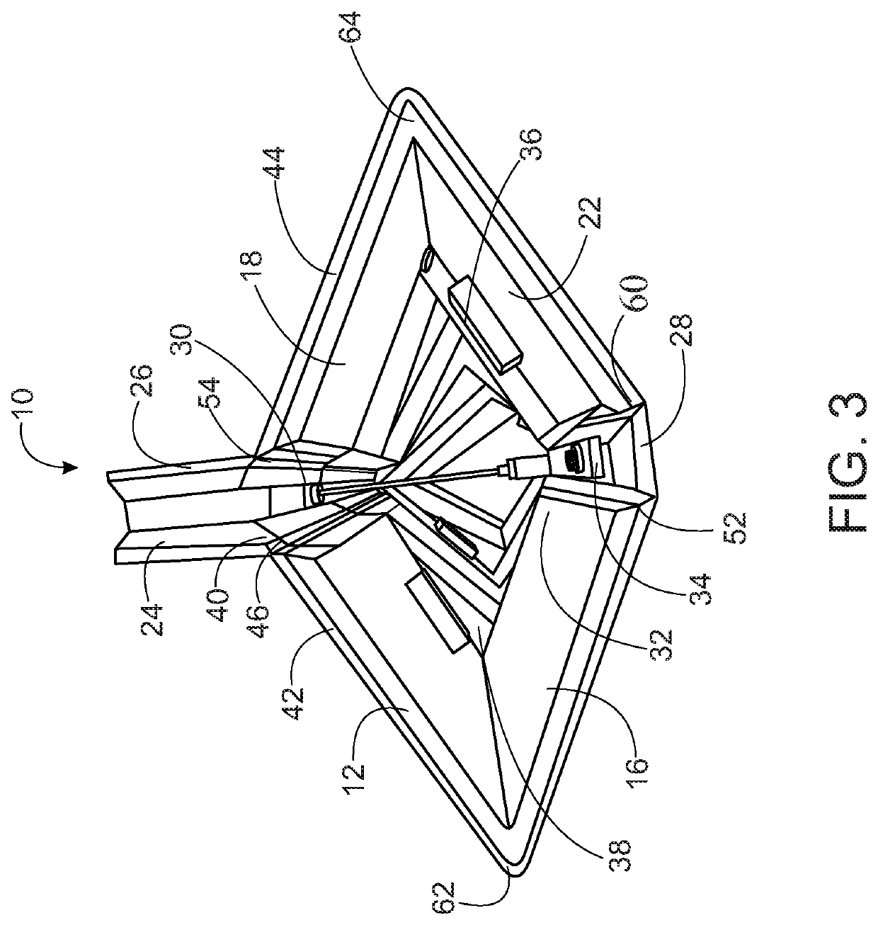
[0025]Once the dynamic environmentally actuated ceiling baffle is manufactured, regardless of the method of attaching the dynamic environmentally actuated ceiling baffle to the ceiling structure, a cable can be attached to the inside bottom of the dynamic environmentally actuated ceiling baffle, such that when the cable is retracted or withdrawn, the bottom portion of the dynamic environmentally actuated ceiling baffle will move towards the top portion thereby creating an air gap as the sidewall portions begin to bend. As more cable is taken up, the dynamic environmentally actuated ceiling baffle will move to the largest air gap and theoretically the most optimal position for the environment. Conversely, as more cable is let out, the bottom portion will move away from the top portion, and at the furthest distance, the dynamic environmentally actuated ceiling baffle will have collapsed and reduced or eliminated the air gap.

Problems solved by technology

However, either for cost or design purposes, many designs provide that the mechanical and electrical equipment are to be seen and not hidden.
Although the exposed ceiling may be a function of the design appeal, quite often an exposed ceiling creates acoustic problems, especially in large industrial rooms.
If there are a lot of workers or machinery, the room can become quite loud.
However, none of these structures or any other that Applicant is currently aware of, provide a dynamic environmentally actuated ceiling baffle, or any type of baffle that is automatically, programmatically, or manually actuated based on environmental surroundings, such as room acoustics, and including the use of sensors, when necessary, to provide input for configuring and reconfiguring the dynamic ceiling baffle to optimize performance.

Method used


Image

  • Apparatus and system for dynamic environmentally actuated ceiling baffle and methods thereof
  • Apparatus and system for dynamic environmentally actuated ceiling baffle and methods thereof
  • Apparatus and system for dynamic environmentally actuated ceiling baffle and methods thereof

Examples


Embodiment Construction

[0033]As stated herein, the objective of the present disclosure is to provide an improved dynamic environmentally actuated ceiling baffle, and an improved dynamic environmentally actuated ceiling baffle system, along with improved methods for manufacturing and installing the ceiling baffles and creating the dynamic environmentally actuated ceiling baffle system.

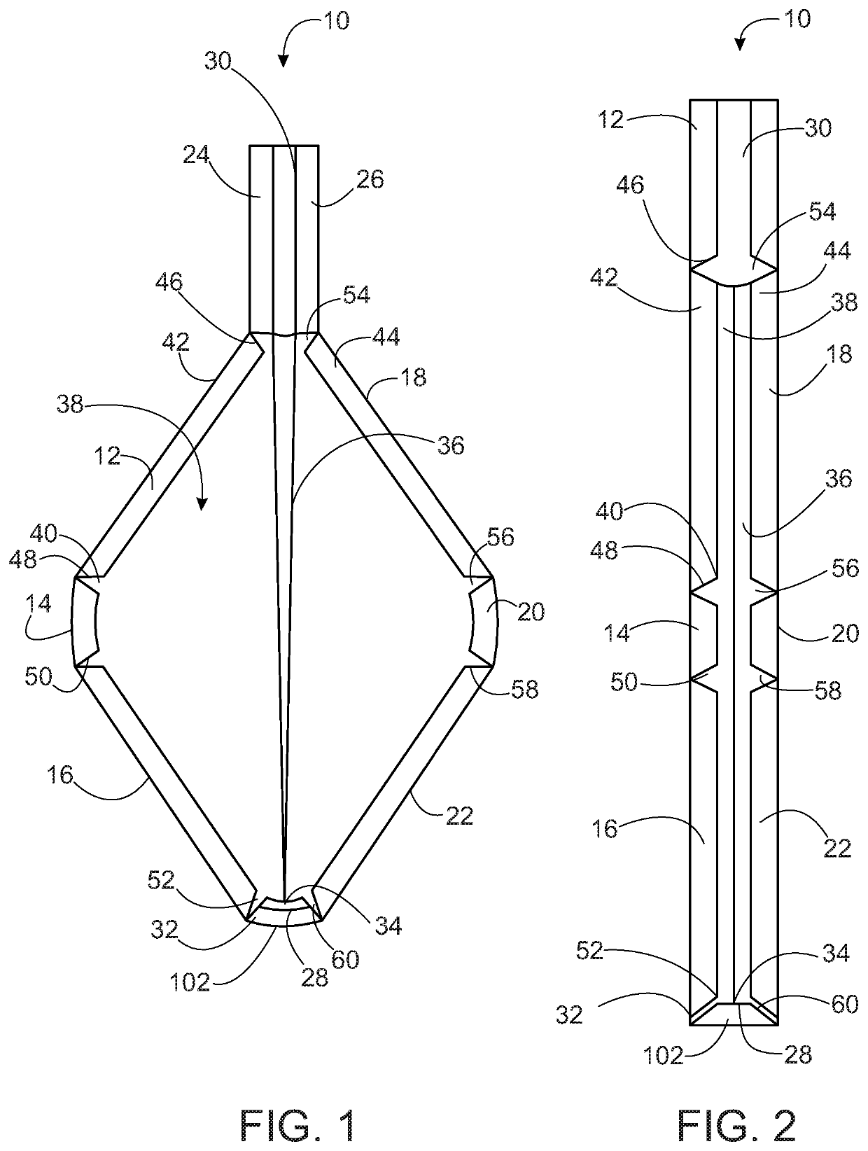
[0034]Referring to the drawings, wherein like reference numerals refer to the same or similar features in the various views, FIGS. 1 through 5 show different views of the improved dynamic environmentally actuated ceiling baffle 10 in the preferred embodiment. FIGS. 1 and 2 show side views of the dynamic environmentally actuated ceiling baffle 10 of the present disclosure, which in the preferred embodiment comprises a first upper sidewall 12, a first middle sidewall 14 and a first lower sidewall 16. The dynamic environmentally actuated ceiling baffle 10 also comprises a second upper sidewall 18, a second middle sidewall 20 and...


PUM


Abstract

A dynamic environmentally actuated ceiling baffle and system that incorporates sidewalls with cuts or kerfs, top and bottom portions and sensors to automatically, programmatically and manually properly configure the ceiling baffle for optimal noise reduction based on the environment or the needs of the user, and that can be quickly and easily installed onto ceiling structures using integrated locks, cables or magnets, to produce a dynamic environmentally actuated ceiling baffle system, and to provide an aesthetically pleasing image, along with a reduction in unwanted noise and / or room acoustics, using the programmed or manual actuation to tune the ceiling baffle to respond appropriately to the acoustic need.

Description

CROSS-REFERENCE TO RELATED APPLICATIONS[0001]This application claims priority to U.S. Provisional Patent Application No. 63 / 143,185, filed Jan. 29, 2021, entitled APPARATUS AND SYSTEM FOR DYNAMIC ENVIRONMENTALLY ACTUATED CEILING BAFFLE AND METHODS THEREOF, which is hereby incorporated by reference in its entirety as though fully set forth herein.FIELD OF THE INVENTIONa. Technical Field[0002]The present disclosure relates to a dynamic environmentally actuated ceiling baffle apparatus and systems, along with the methods for manufacturing, installing and using the dynamic environmentally actuated ceiling baffles. In particular, the present disclosure relates to dynamic environmentally actuated ceiling baffles and systems that incorporate inputs from the system or users based on the environment, including room acoustics, to properly configure and reconfigure the dynamic environmentally actuated ceiling baffle to counter or respond to the environment, using the programmed or manual actua...

Claims


Application Information

Patent Timeline
Patent Type & Authority Applications(United States)
IPC IPC(8): G10K11/162E04B1/99E04B9/00E04B9/04E04B9/18E04B9/24
CPCG10K11/162E04B1/994E04B9/003E04B9/248E04B9/18E04B9/247E04B9/0414
Inventor HEADLEY, DUSTIN
Owner TURF DESIGN INC
Why Eureka
Try Eureka