
Stator for axial flux machine

a technology of axial flux and electric machines, which is applied in the direction of dynamo-electric components, synchronous machines with stationary armatures and rotating magnets, cooling/ventilation arrangements, etc., can solve the problems of increasing the power rating of the machine, increasing the difficulty of cooling typical yasa machines, and limited power source volum

Pending Publication Date: 2022-08-04
YASA LIMITED
View PDF0 Cites 0 Cited by
  • Summary
  • Abstract
  • Description
  • Claims
  • Application Information

AI Technical Summary

Benefits of technology

The invention is a machine with a larger stator that can produce more power compared to a machine with a conventional stator of the same size. The stator is enclosed within a housing that allows for an increase in the size of the stator coils and poles. The housing has a reduced radial dimension compared to conventional stators, which allows for smaller machines to have higher power output. The outer circumferential side of the stator housing may abut stator bars, blocking the flow of the cooling liquid and causing the cooling fluid to be forced between adjacent stator bars. The housing may also be flattened to reduce its out dimension.

Problems solved by technology

However the volume available for power source, transmission and ancillary components is limited and a variety of factors including power storage puts further pressure on designers to increase power density of electric machines for space and performance gains.
Particularly for axial flux, segmented armature formats increasing a machine's power rating raises additional problems because the interior of these machines is already designed for high power operation, often reliant on effective liquid coolant flow.
Typical YASA machines are difficult to cool because they lack a stator yoke through which heat can be conducted away from the stator.
Prior art machines have immersed stator coils in flowing liquid coolant contained within a stator housing, significantly increasing heat dissipation and hence power delivery.

Method used


Image

  • Stator for axial flux machine
  • Stator for axial flux machine
  • Stator for axial flux machine

Examples


Embodiment Construction

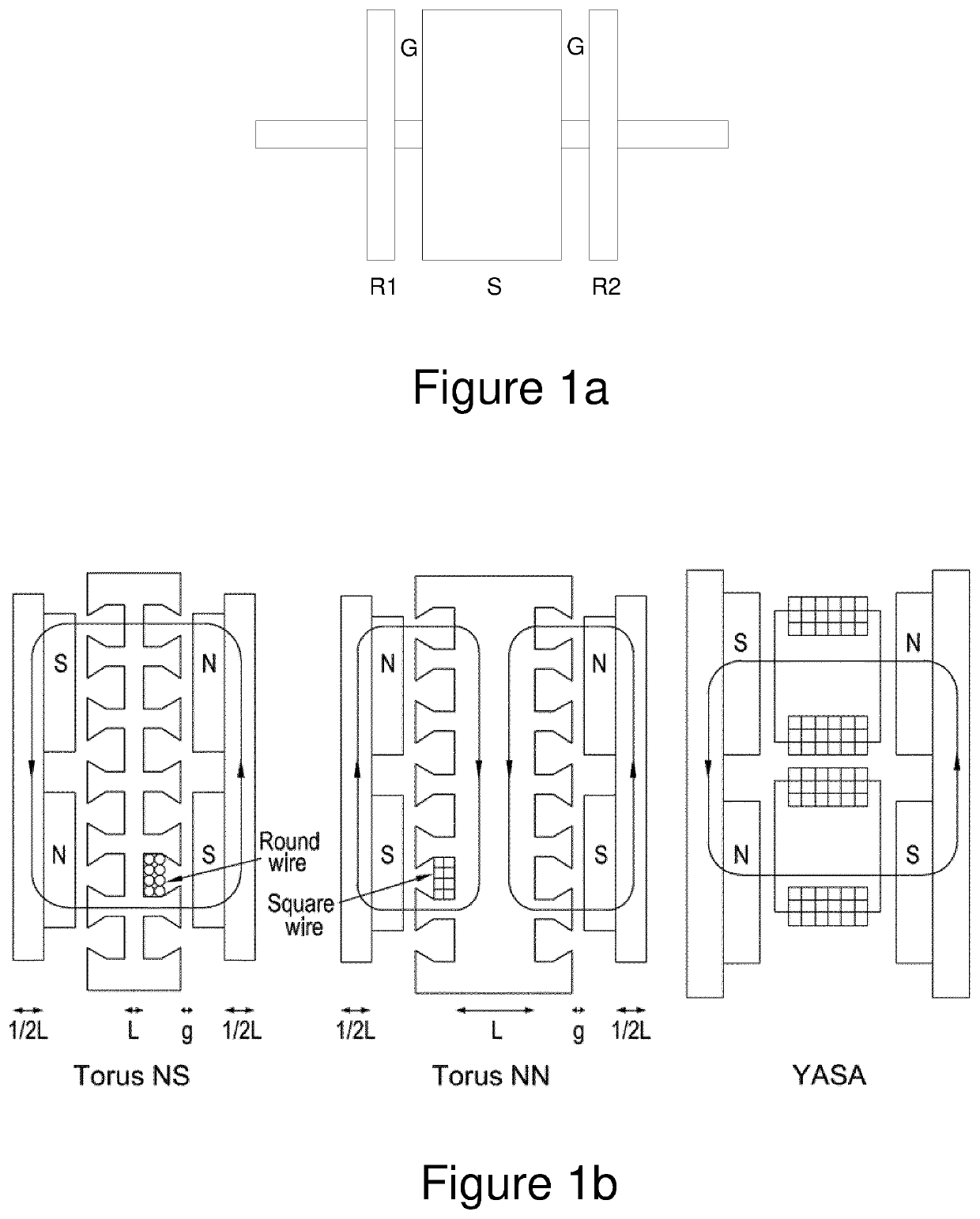
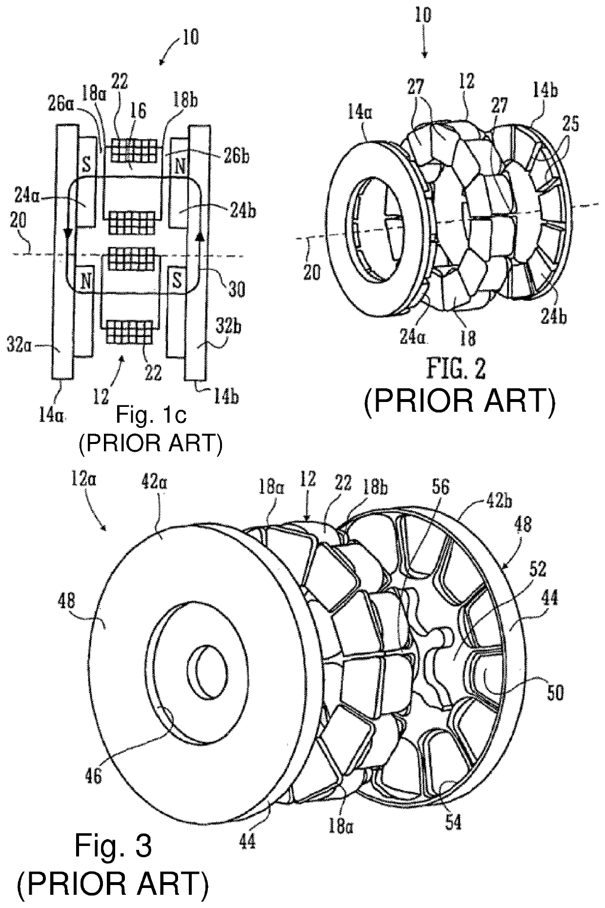
[0047]We will first discuss the background of the arrangement of axial flux machines, which is an example use of the stator of the present invention. Referring first to FIGS. 1c, 2 and 3, which are taken from our PCT application WO2012 / 022974, FIG. 1c shows a schematic illustration of a yokeless and segmented armature machine 10.

[0048]The machine 10 comprises a stator 12 and two rotors 14a,b. The stator 12 is a collection of separate stator bars 16 spaced circumferentially about a rotation axis 20 of the rotors 14a,b. Each bar 16 has its own axis (not shown) which is preferably, but not essentially, disposed parallel to the rotation axis 20. Each end of each stator bar is provided with a shoe 18a,b which serves a physical purpose of confining a coil stack 22, which stack 22 is preferably of square / rectangular section insulated wire so that a high fill factor can be achieved. The coils 22 are connected to an electrical circuit (not shown) that, in the case of a motor, energizes the c...


PUM


Abstract

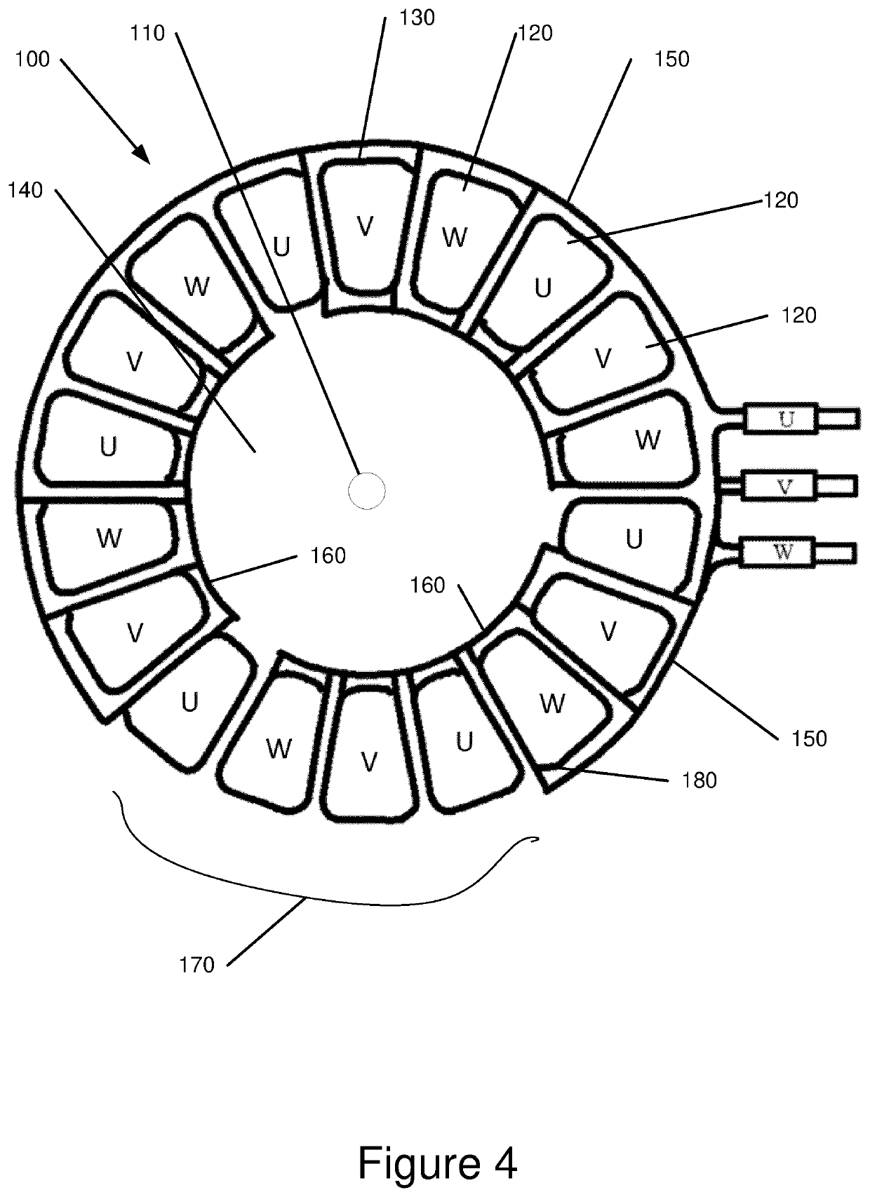
A stator having a plurality of stator bars disposed circumferentially at intervals around an axis is provided. Each of the stator bars has a set of windings wound therearound for generating a magnetic field generally parallel to the axis. A plurality of radially outwardly disposed electrical interconnects for connecting two or more windings together are provided radially outwardly of the plurality of stator bars and extending circumferentially along at least a portion of the outer periphery of the stator bars. A plurality of radially inwardly disposed electrical interconnects for connecting two or more windings together are also provided radially inwardly of the stator bars and extending circumferentially along at least a portion of the inner periphery of the stator bars. The outer periphery of the stator is devoid of radially outwardly disposed interconnects along one or more portions.

Description

FIELD OF THE INVENTION[0001]This invention relates to the construction of electrical machines, in particular stators used for axial flux electric machines used as motors and generators.BACKGROUND OF THE INVENTION[0002]There is a need to improve the power density of electric machines such as motors and generators. One reason for this is the increasing focus on electrically driven vehicles, including land vehicles and aircraft. However the volume available for power source, transmission and ancillary components is limited and a variety of factors including power storage puts further pressure on designers to increase power density of electric machines for space and performance gains.[0003]Improving power density of electric machines has often been directed towards one or more of cooling methods, motor topology and materials usually to enable higher ampere turns. Though these approaches have seen significant advances, there remains a strong incentive to further improve power density. Pa...

Claims


Application Information

Patent Timeline
Patent Type & Authority Applications(United States)
IPC IPC(8): H02K21/24H02K9/19H02K5/20H02K3/28H02K1/2798
CPCH02K21/24H02K9/19H02K1/2798H02K3/28H02K5/203H02K1/2793H02K3/04
Inventor WOOLMER, TIMHILLMAN, TOM
Owner YASA LIMITED
Learn More