Drivetrain assembly

a technology for driving trains and assembly parts, applied in the direction of mechanical equipment, machines/engines, fastening means, etc., can solve the problems of difficult mounting of such a form-fitting ring, high manufacturing cost, and large axial load on bearings

Pending Publication Date: 2022-08-11
GAMESA INNOVATION & TECH SA
View PDF19 Cites 0 Cited by
  • Summary
  • Abstract
  • Description
  • Claims
  • Application Information

AI Technical Summary

Benefits of technology

[0025]FIG. 2 shows a more detailed vie

Problems solved by technology

During operation of the wind turbine, the bearing is subject to very large axial loads, particularly in the “downstream” direction.
However, it can be difficult to mount such a form-fit r

Method used


Image

  • Drivetrain assembly
  • Drivetrain assembly
  • Drivetrain assembly

Examples


Embodiment Construction

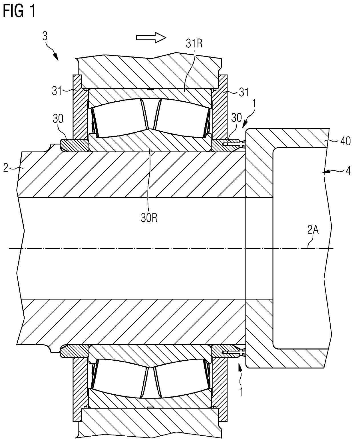
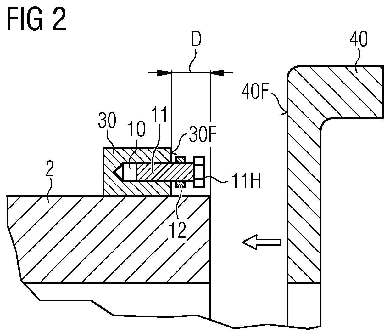
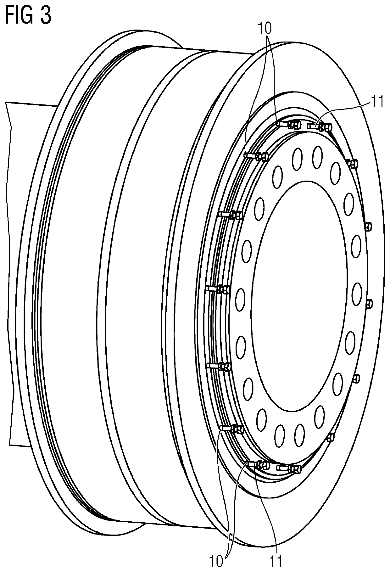
[0031]FIG. 1 shows a cross-section through a relevant region of a wind turbine drivetrain, showing details at the junction between the rotor shaft 2 and a gearbox unit 4. The gearbox unit 4 is mounted by bolts (not shown) to the rotor shaft 2. The diagram shows a bearing unit 3 in place about the shaft 2. The bearing unit 3 comprises a stationary outer ring 31R and outer housing part 31, and a rotating inner ring 30R and inner housing part 30. In this exemplary embodiment, the bearing unit 3 is constructed as a double-row spherical roller bearing.

[0032]An interference fit between the bearing unit 3 and rotor shaft 2 ensures that the inner ring 30R and inner housing part 30 move as one with the rotating shaft 2. The stationary outer housing part 31 of the bearing unit 3 can be connected to another stationary part, for example to a bedframe or to the nacelle, for example.

[0033]During operation of the wind turbine, the bearing unit 3 is subject to various types of load and care must be...


PUM


Abstract

Provided is a drivetrain assembly including a rotor shaft; a bearing unit mounted about the rotor shaft; and a further drivetrain component connected to an end of the rotor shaft, wherein an annular face of the further drivetrain component is arranged opposite an annular face of the bearing unit with a distance between the annular faces. The drivetrain assembly is characterized by an annular arrangement of tapped holes formed in a first of the two opposing annular faces; a plurality of bolts, wherein each bolt includes a bolt shaft threaded into a tapped hole, a lock nut threaded onto the bolt shaft and tightened against the first annular face; and a bolt head arranged to make contact with the second of the two opposing annular faces. Also provided is a wind turbine including a such a drivetrain assembly; and a method of assembling such a drivetrain.

Description

CROSS-REFERENCE TO RELATED APPLICATIONS[0001]This application claims priority to EP Application No. 21382107.7, having a filing date of Feb. 11, 2021, the entire contents of which are hereby incorporated by reference.FIELD OF TECHNOLOGY[0002]The following relates to a drivetrain assembly, a wind turbine comprising such a drivetrain assembly, and a method of assembling such a drivetrain.BACKGROUND[0003]The drivetrain of a wind turbine comprises an aerodynamic rotor with rotor blades that convert wind energy into a rotating motion of a hub and rotor shaft. The rotating shaft turns the rotor of an electrical machine so that electricity is generated.[0004]A large bearing is required between the rotor shaft and the stationary supporting structure. The inner race of the bearing is generally connected to the rotating shaft by a press fit, also referred to as a friction fit or interference fit. During operation of the wind turbine, the bearing is subject to very large axial loads, particula...

Claims


Application Information

Patent Timeline
IPC IPC(8): F03D15/00F03D80/70F16B5/02
CPCF03D15/00F03D80/70F16B5/02F05B2240/50F05B2260/4031F05B2260/301F05B2230/60F03D13/10F05B2240/60F05B2230/80F05B2260/30
Inventor ALBIZUA MACUA, JUANDURAND, MICKAËL
Owner GAMESA INNOVATION & TECH SA
Why Eureka
Try Eureka