Supercharge Your Innovation With Domain-Expert AI Agents!

Ultrasonic resonator support structure and ultrasonic vibration machining apparatus

a technology of ultrasonic resonator and support structure, which is applied in the direction of mechanical vibration separation, manufacturing tools, metal working apparatus, etc., can solve the problems of prolonged machining time and restricted cutting speed, and achieve the effect of improving durability, improving maintenance efficiency, and simplifying the support of the second booster sid

Active Publication Date: 2022-08-25
TAKATA CORPORATION
View PDF9 Cites 0 Cited by
  • Summary
  • Abstract
  • Description
  • Claims
  • Application Information

AI Technical Summary

Benefits of technology

The ultrasonic resonator support structure and ultrasonic vibration machining apparatus described in this patent offer improved durability and stability, as well as efficient maintenance and operation. The support structure includes a rolling bearing mechanism and a gas bearing mechanism, which simplifies the second booster side and reduces the load on the rolling bearing mechanism and the supporting part attached to the first booster. The structure also improves the stability of the ultrasonic resonator and allows for precise positioning during machining operations. Furthermore, the support structure prevents the cutting fluid or shavings from affecting the gas bearing mechanism, and thus ensures durability and operational stability. The ultrasonic vibration machining apparatus includes the support structure and is capable of securely supporting the ultrasonic resonator and stably operating, regardless of the disposition state.

Problems solved by technology

Thus, there is a problem that the cutting speed is restricted and the machining time is prolonged.

Method used


Image

  • Ultrasonic resonator support structure and ultrasonic vibration machining apparatus
  • Ultrasonic resonator support structure and ultrasonic vibration machining apparatus
  • Ultrasonic resonator support structure and ultrasonic vibration machining apparatus

Examples


Embodiment Construction

[0034]An embodiment of the present invention will be subsequently described with reference to the accompanying drawings to provide an understanding of the present invention.

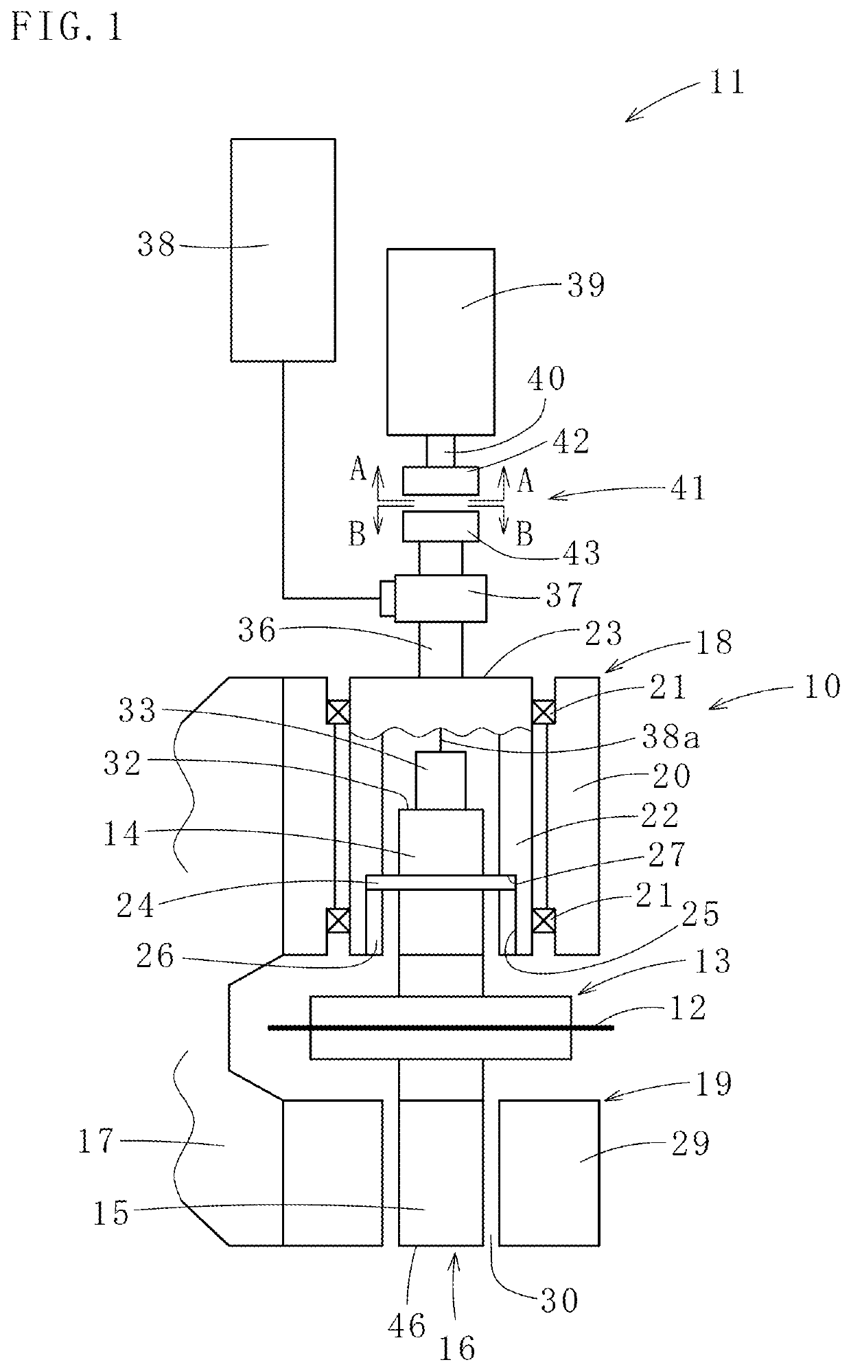
[0035]FIG. 1 illustrates an ultrasonic vibration machining apparatus 11 including an ultrasonic resonator support structure 10 according to the embodiment of the present invention. The ultrasonic vibration machining apparatus 11 performs machining operations (e.g. cutting, grinding, or the like) of the hard and brittle materials such as silicon wafers by using a rotating blade (an example of the machining tool) 12 that rotates while ultrasonically vibrating in the radial directions. As shown in FIG. 1, the ultrasonic resonator support structure 10 is a structure configured to support an ultrasonic resonator 16 at both sides such that the ultrasonic resonator 16 is rotatable to a holder 17, in which the ultrasonic resonator 16 includes an disk-like ultrasonic horn 13 with the rotating blade 12 attached and a first...


PUM

PropertyMeasurementUnit
outer circumferenceaaaaaaaaaa
lengthaaaaaaaaaa
wave lengthaaaaaaaaaa

Abstract

An ultrasonic resonator support structure 10 including a holder 17 supports an ultrasonic resonator 16 at both sides such that the ultrasonic resonator 16 is rotatable to the holder 17. The ultrasonic resonator 16 includes an ultrasonic horn 13 with a machining tool 12 attached, and a first booster 14 and a second booster 15 coaxially fixed one by one to both ends in the axial directions of the ultrasonic horn 13. The holder 17 has a rolling bearing mechanism 18 that rotatably supports the first booster 14 side of the ultrasonic resonator 16 and a gas bearing mechanism 19 that rotatably supports the second booster 15 side of the ultrasonic resonator 16.

Description

TECHNICAL FIELD[0001]The present invention is related to an ultrasonic resonator support structure used mainly for machining hard and brittle materials such as semiconductor wafers (i.e. silicon wafers), and related to an ultrasonic vibration machining apparatus.BACKGROUND ART[0002]Patent literature 1 discloses an ultrasonic vibration cutting apparatus for cutting the wafers (i.e. the workpiece to be cut), and in the ultrasonic vibration cutting apparatus, a disk-like cutting blade (an example of the machining tool) is attached to one end of an ultrasonic resonator (i.e. an ultrasonic vibration rotating mechanism) disposed such that the axial directions of the ultrasonic resonator are the horizontal directions. This ultrasonic vibration cutting apparatus cuts the wafers by linearly moving the cutting blade while rotating the cutting blade and applying radial-direction ultrasonic vibrations to the cutting blade.[0003]Since patent literature 1 has a cantilever structure where the cutt...

Claims


Application Information

Patent Timeline
Patent Type & Authority Applications(United States)
IPC IPC(8): B06B1/02B06B3/00B24B1/04B28D1/00B28D5/02
CPCB06B1/02B06B3/00B24B1/04B28D1/00B28D5/02B23B2270/10B28D5/047B28D5/0058B23C2270/10B23C3/04B24B55/00B28D5/022
Inventor YOTSUMOTO, KEIICHIMORI, NOBUHIROKUBO, NAOKIMATSUYAMA, HIRONOBU
Owner TAKATA CORPORATION
Features
  • R&D
  • Intellectual Property
  • Life Sciences
  • Materials
  • Tech Scout
  • Unparalleled Data Quality
  • Higher Quality Content
  • 60% Fewer Hallucinations
Learn More