

Integrated Steering Suspension Module For A Vehicle
a technology of steering suspension module and vehicle, which is applied in the direction of steering linkage, mechanical apparatus, transportation and packaging, etc., can solve the problems of high cost, difficult or at least complex, manufacturing process such as bending or deep drawing, and the inability to achieve complex articulated shapes, etc., to achieve significant weight reduction and constructive simplification, the effect of high reliability
- Summary
- Abstract
- Description
- Claims
- Application Information
AI Technical Summary
Benefits of technology
Problems solved by technology
Method used
Image

Examples
embodiment 1
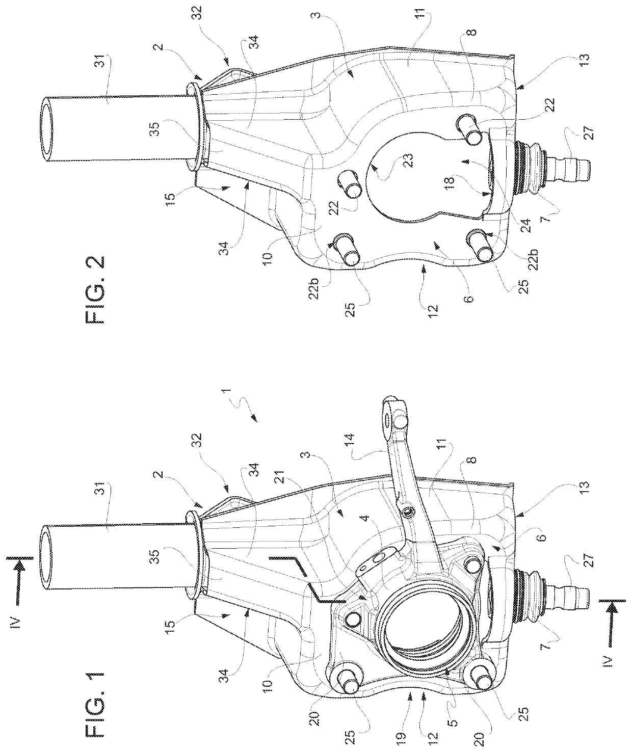
[0023]In particular, the embodiment 1, not limitedly shown, of the suspension module according to the invention is of the McPherson architecture type, but it is clear that what will be said is applicable to any other type of suitable suspension architecture.
[0024]The integrated suspension module 1 comprises a shock absorber strut 2, a suspension upright 3 bearing the shock absorber strut 2 at the top, and an outer ring 4 of a wheel hub unit 5 or a rolling bearing forming part of the wheel hub unit 5.
[0025]The wheel hub unit 5 is shown for ease of simplicity only with parts removed, the removed parts being known in themselves.
[0026]The outer ring 4 is fixed integral to a front face 6 of the suspension upright 3. The front face 6 is configured to be facing the outside of the vehicle, in use, thus towards the wheel mounted (in a manner known and not shown for ease of simplicity) on the wheel hub unit 5 on a side opposite to the suspension upright 3.
[0027]The steering suspension module ...
first embodiment
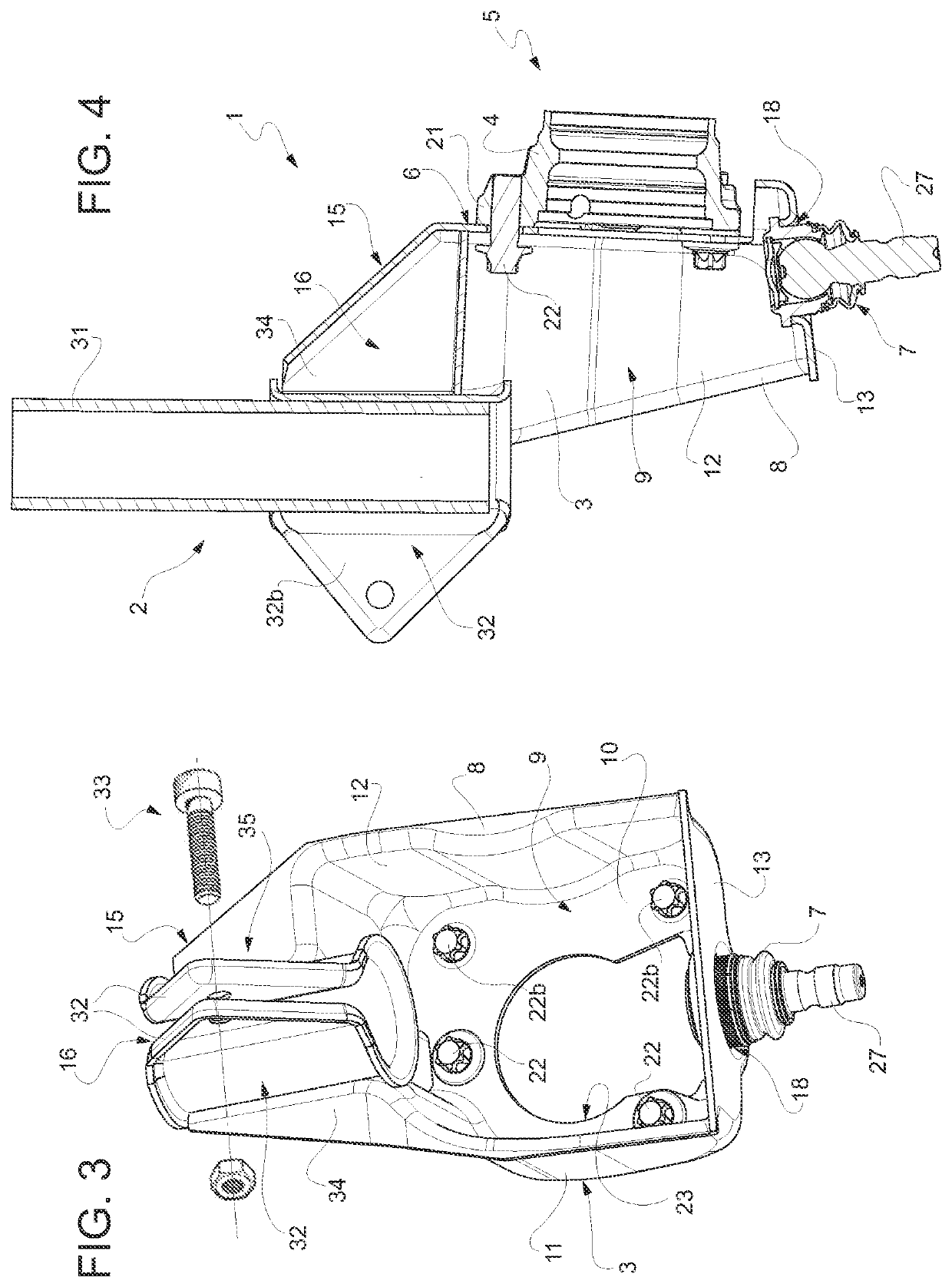
[0055] described, in module 1 the mentioned second seat or interface comprises a through hole 18 drilled through the third side wall 13 of the cup-shaped body 8 and in which hole 18 the ball joint 7, made as an independent unit, is fitted through by interference fit, so as to (FIGS. 3 and 4) project cantilevered from the side wall 18 both inwardly of the cup-shaped body 8, within the concavity 9, and outwardly of the cup-shaped body 8, with one end thereof 27 configured to mate with the mentioned lower control arm of the known and not shown suspension system.
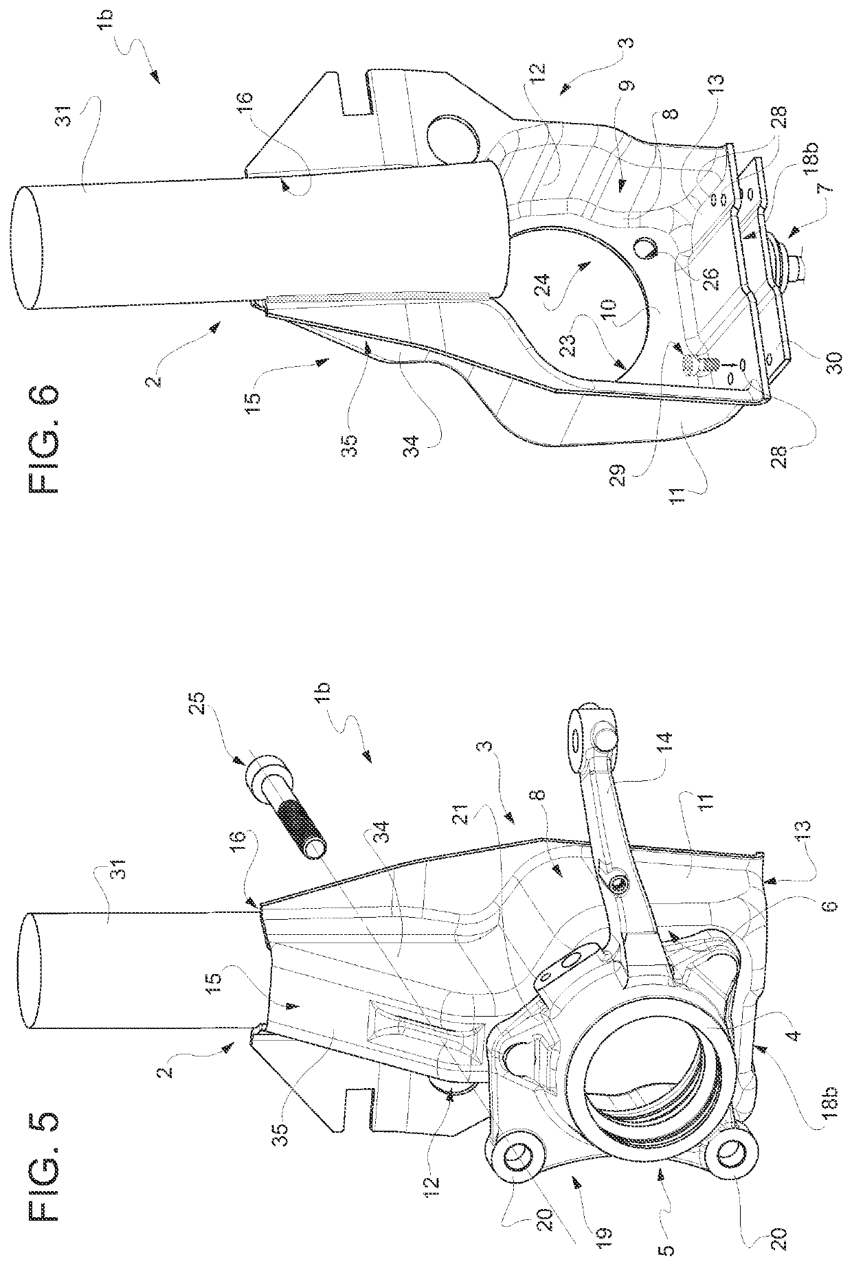
[0056]According to the embodiment lb, on the other hand (FIGS. 5 and 6), the second seat or interface comprises a coining 18b (in the example shown) or through opening (similar to the hole 18 of the module 1) obtained in the third side wall 13 and configured to receive the ball joint 7 made as an independent unit so that the latter protrudes cantilevered from the side wall 13, on a side opposite to the concavity 9 of the cup-sha...
PUM
 Abstract
Description
Claims
Application Information