
Method and apparatus for obtaining angle information of reference signal

a reference signal and angle information technology, applied in diversity/multi-antenna systems, instruments, transmission path sub-channel allocation, etc., can solve problems such as redundancy in wireless resources and reducing cell coverag

Active Publication Date: 2022-09-08
LOCAILA INC
View PDF4 Cites 0 Cited by
  • Summary
  • Abstract
  • Description
  • Claims
  • Application Information

AI Technical Summary

Benefits of technology

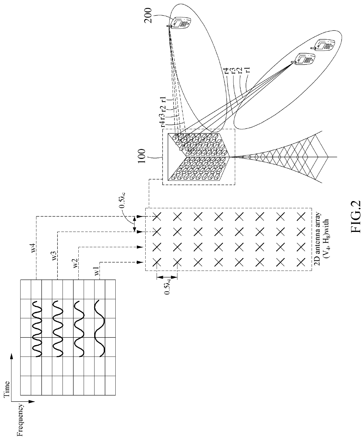
This patent text describes a method that allows a user device (metal device) to easily calculate the difference in travel distance or delay time between signals received from different antennas. This allows the device to determine the angle of arrival (AoD) of a reference signal. This information can be used by a base station to improve its communication with the device, by optimizing the beam sweeping procedure. This can save time and reduce the use of wireless resources.

Problems solved by technology

As a frequency band used for wireless communication becomes higher in a gradual manner, pathloss of radio wave increases, which may lead to reducing cell coverage.
Therefore, wireless resources may be redundantly used.

Method used


Image

  • Method and apparatus for obtaining angle information of reference signal
  • Method and apparatus for obtaining angle information of reference signal
  • Method and apparatus for obtaining angle information of reference signal

Examples


Embodiment Construction

[0033]Various modifications and changes may be made to the present disclosure and the disclosure may include various example embodiments. Specific example embodiments are described in detail with reference to the accompanying drawings. The example embodiments, however, may be embodied in various different forms, and should not be construed as being limited to only the specific example embodiments. Rather, the example embodiments should be understood to include all of the modifications, equivalents, and substitutions included in the spirit and technical scope of the disclosure.

[0034]Although the terms “first,”“second,” etc., may be used herein to describe various components, the components should not be limited by these terms. These terms are only used to distinguish one component from another component. For example, a first component may also be termed a second component and, likewise, a second component may be termed a first component, without departing from the scope of this discl...


PUM


Abstract

Provided is a method of acquiring angle information of a reference signal performed by a user equipment (UE), the method including receiving a reference signal from a base station including a plurality of patch antennas; acquiring phase information depending on a carrier frequency of the reference signal based on received data of the reference signal measured at a plurality of sample times; and calculating an angle of departure (AoD) of the reference signal based on the phase information depending on the carrier frequency.

Description

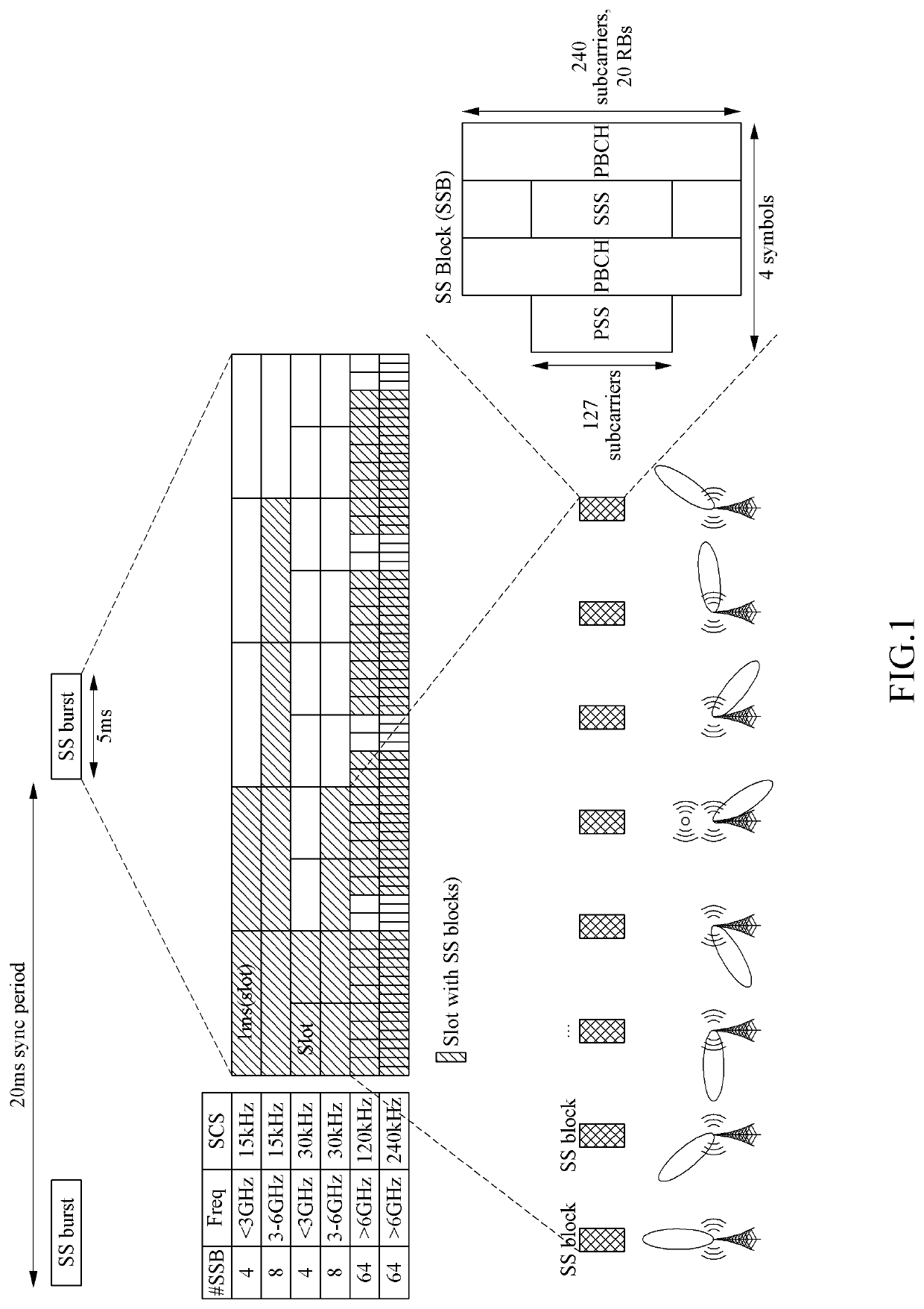
BACKGROUND1. Field[0001]The present disclosure of the following description relates to a method and apparatus for acquiring angle information of a reference signal received at a user equipment (UE), and more particularly, to a method and apparatus for determining a scanning direction of a beam transmitted to a UE based on angle information of a reference signal.2. Related Art[0002]A communication system may include a core network, for example, a mobility management entity (MME), a serving gateway (SGW), a packet data network (PDN) gateway (PGW), a base station (e.g., a macro base station, a small base station, and a relay), a user equipment (UE), and the like. Communication between the base station and the UE may be performed using a variety of radio access technology (RAT), for example, 4-th generation (4G) communication technology, 5-th generation (5G) communication technology, wireless broadband (WiBro) technology, wireless local area network (WLAN) technology, and wireless perso...

Claims


Application Information

Patent Timeline
Patent Type & Authority Applications(United States)
IPC IPC(8): G01S3/46H04L5/00H04B7/06
CPCG01S3/46H04L5/0048H04B7/0695H04B7/0617G01S1/08G01S1/045
Inventor CHO, JAIHYUNG
Owner LOCAILA INC
Learn More