Building System Including Concrete Formwork Using Concrete Shells

a technology of building system and concrete shell, which is applied in the direction of building components, walls, manufacturing tools, etc., can solve the problems of difficulty in maintaining quality and precision in the resulting cured concrete, assembly and subsequent disassembly of the concrete formwork, and high cost and time consumption

Pending Publication Date: 2022-09-15
ASCENT PROJECTS INC
View PDF0 Cites 0 Cited by
  • Summary
  • Abstract
  • Description
  • Claims
  • Application Information

AI Technical Summary

Benefits of technology

[0019]The system according to the present invention resolves many issues with prior systems described above. The precast concrete formwork panels are manufactured in controlled environment with greater precision and include flexibility in their application to meet a great variety of design requirements. The precast forms are much lighter than the traditional precast panels and, therefore, the transportation and installation costs are reduced. The system allows elimination of “cold bridges” when an insulation layer is incorporated into the shells before pouring the concrete core. Electrical and other conduits could be placed at plant and finished at field.
[0021]In the field, the connection between various structural members is provided by the field placed concrete in combination with reinforcement incorporated within the precast shells and, additionally, field placed reinforcement wherever required. Thus, the need for welded or bolted connections and further protection against the elements is eliminated.

Problems solved by technology

Due to varying environmental factors at each different building location, it can be difficult to maintain quality and precision in the resulting cured concrete.
The assembly and subsequent disassembly of the concrete formwork can also be costly and time consuming.
The resulting precast panels are heavy concrete members, which require costly transportation and erection using suitable handling equipment.
These joints should be further protected against the elements, thus increasing cost and construction time.
The resulting solid concrete structure includes the inevitable creation of cold bridges, especially in the area of the joints where continuation of the thermal insulation is dubious or impossible.

Method used


Image

  • Building System Including Concrete Formwork Using Concrete Shells
  • Building System Including Concrete Formwork Using Concrete Shells
  • Building System Including Concrete Formwork Using Concrete Shells

Examples


Embodiment Construction

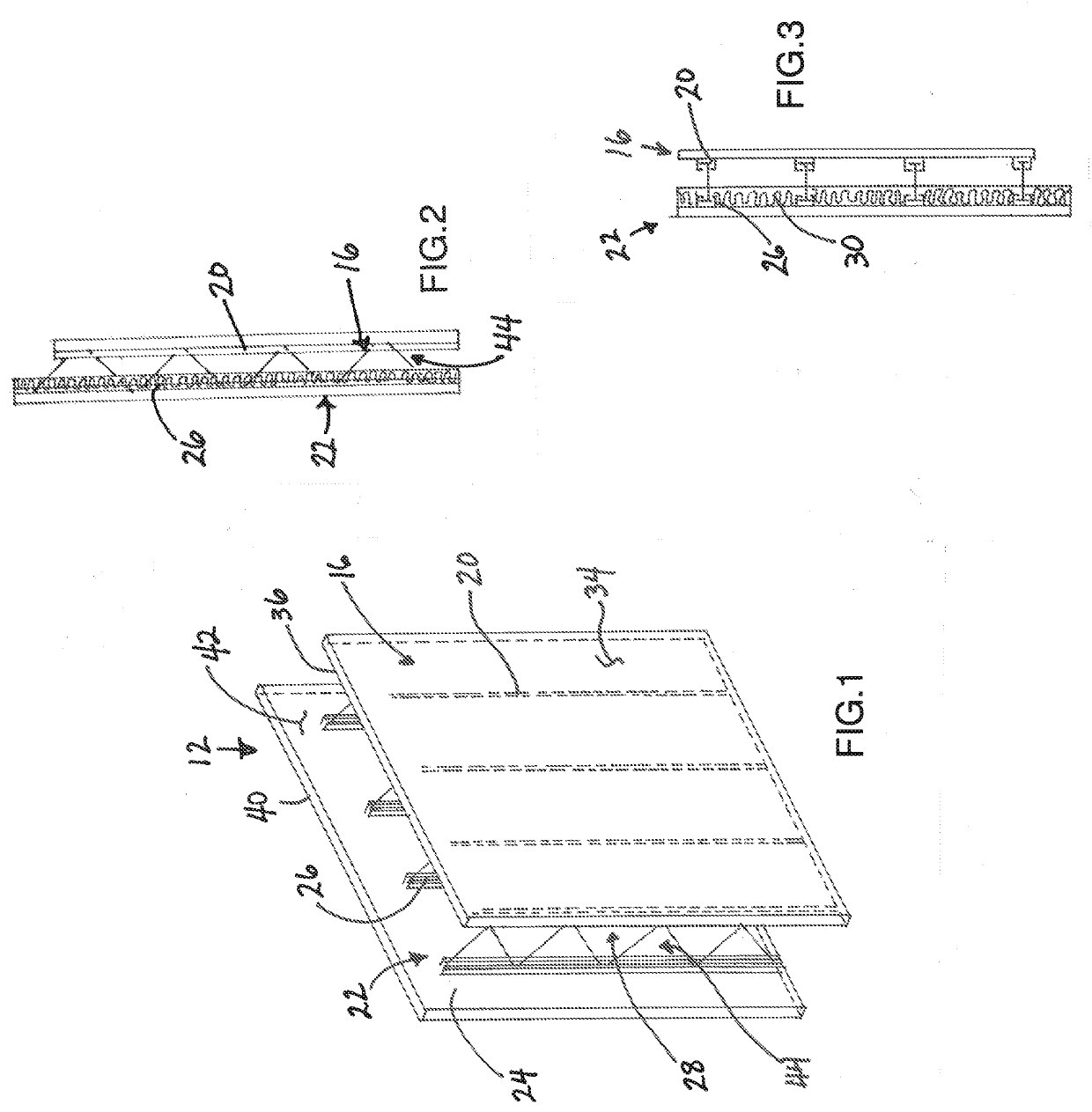
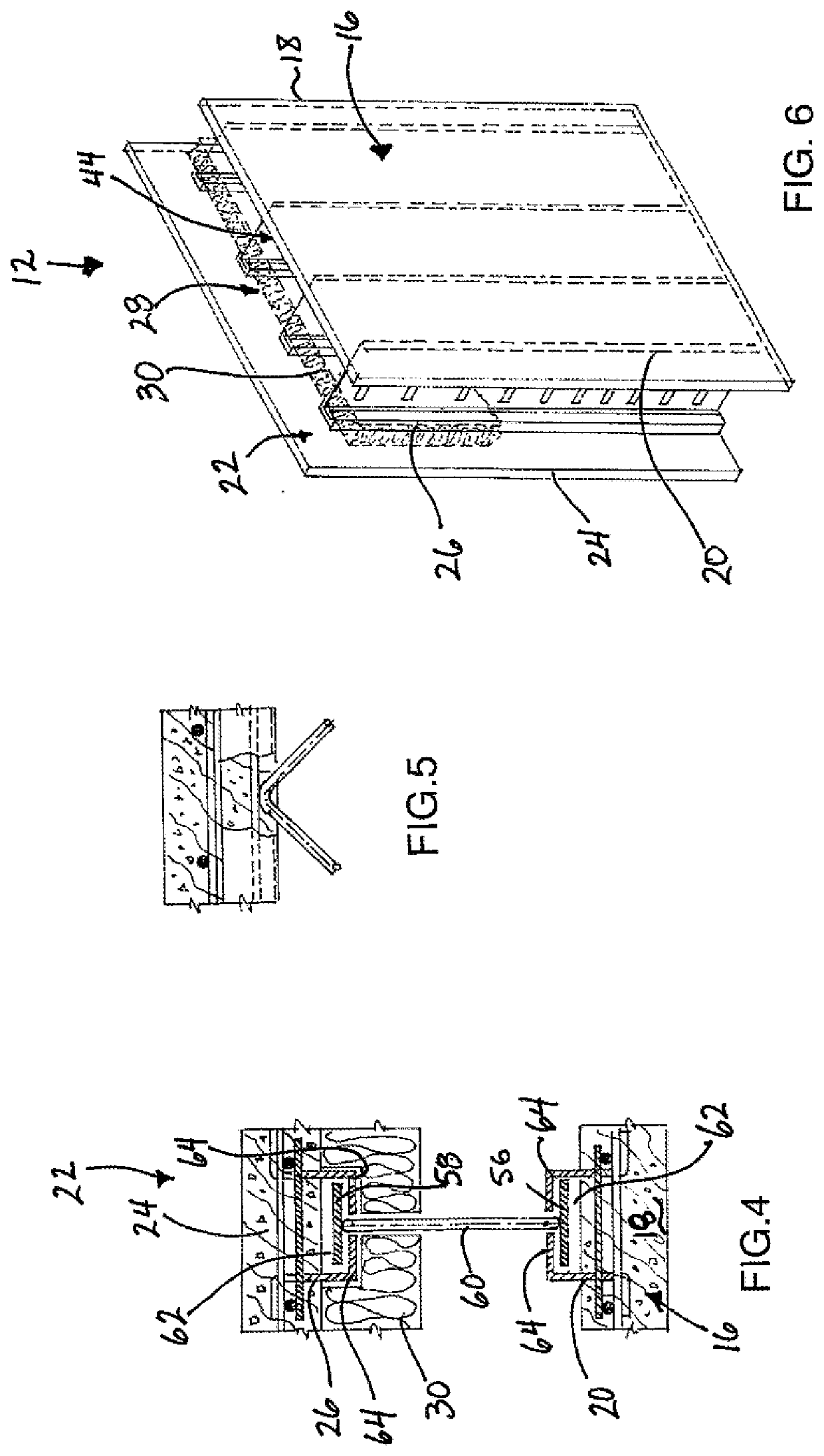
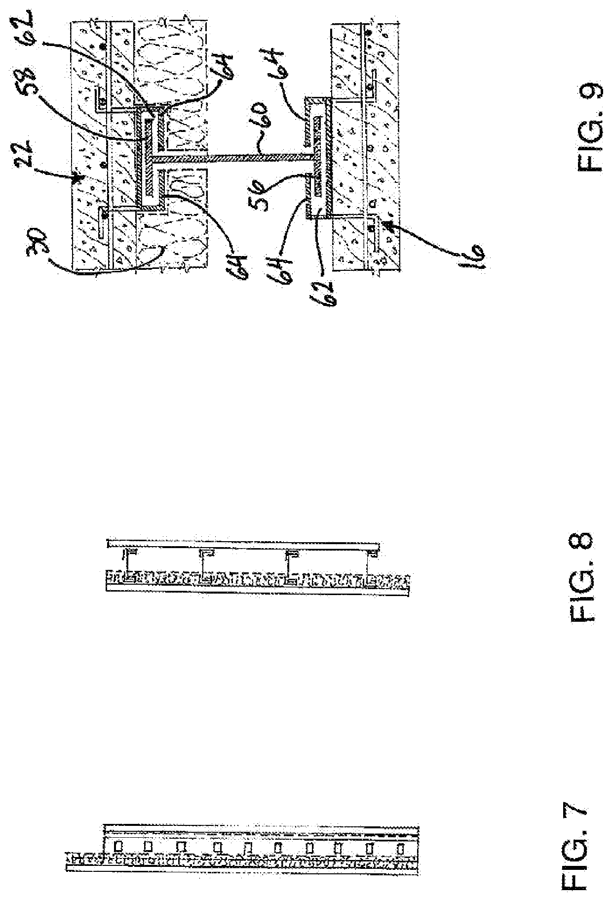
[0083]Referring to the accompanying figures there is illustrated a building system generally comprised of a plurality of wall assemblies 12 and optional floor assemblies 14 which are assembled together to form a building structure suitable for receiving occupants and like therein.

[0084]Each wall assembly 12 generally comprises (i) an inner shell 16 formed of a concrete panel 18 with stiffener members 20 embedded therein, (ii) an outer shell 22 formed of a concrete panel 24 with stiffener members 26 embedded therein; and various forms of mechanical couplings between the inner shell and the outer shell in a manner that supports the shells in fixed relation to one another and in spaced apart relation to one another so as to define a mold cavity 28 between the shells that is arranged to receive poured concrete therein. The concrete panels 18 and 24 can be cast in respective molds simultaneously with one another at a first manufacturing location and then mechanically coupled to one anoth...


PUM

PropertyMeasurementUnit
widthaaaaaaaaaa
heightaaaaaaaaaa
thicknessaaaaaaaaaa

Abstract

A wall assembly for a building structure, uses (i) an inner shell cast in a first mold to define a first panel of concrete having a plurality of stiffener members embedded in the concrete so as to be at least partly exposed at the inner side of the panel, and (ii) an outer shell cast in a second mold to define a second panel of concrete having a plurality of stiffener members embedded in the concrete so as to be at least partly exposed at the inner side of the panel. The inner shell and the outer shell are mechanically coupled after casting to define a mold cavity between the inner sides of the panels. Field concrete can be cast into the mold cavity between the inner and outer shells once the wall assembly is mounted on site into position within the building structure.

Description

[0001]This application claims the benefit under 35 U.S.C. 119(e) of U.S. provisional application Ser. No. 63 / 160,147, filed Mar. 12, 2021.FIELD OF THE INVENTION[0002]The present invention relates to a building system having concrete wall and / or floor forms that receive poured concrete therein in which the concrete forms for the walls include inner and outer shells made of precast concrete that are coupled to define a concrete receiving cavity between the inner and outer shells and the concrete form for the slabs consists of bottom shell made of precast concrete receiving the fresh concrete on top. The system is flexible and could be used as a stand alone or in combination with most of the existing building systems for civil and industrial construction as well as infrastructure construction.BACKGROUND[0003]Concrete is a common building material for walls and floors and the like in various types of buildings. Commonly, concrete formworks are assembled at the building site to receive p...

Claims


Application Information

Patent Timeline
Patent Type & Authority Applications(United States)
IPC IPC(8): E04B2/86B28B23/02B28B7/24
CPCE04B2/86B28B23/022B28B7/243E04B2/8641B28B23/028B28B7/085
Inventor DULGUEROV, EMIL IVANOV
Owner ASCENT PROJECTS INC
Why Eureka
Try Eureka