Optical lens system, camera and terminal
a technology of optical lens and lens body, applied in the field can solve the problems of shortening the total optics length, miniaturization of optical lens system, and inapplicability to mobile devices
- Summary
- Abstract
- Description
- Claims
- Application Information
AI Technical Summary
Benefits of technology
Problems solved by technology
Method used
Image

Examples
first embodiment
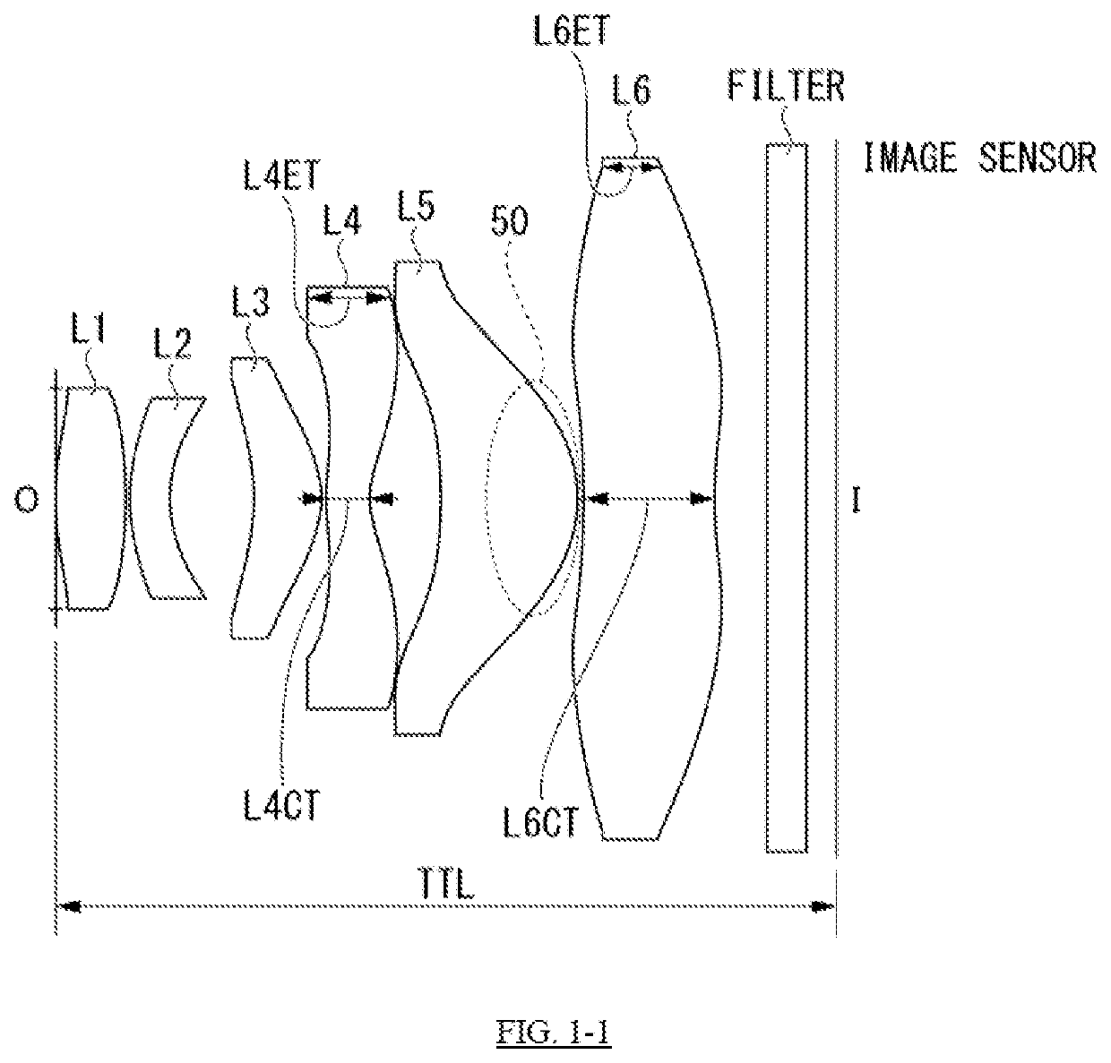
[0049]FIG. 1-1 shows a cross-sectional illustration of a first embodiment of a six-piece optical lens system.FIG. 1-1 also shows a filter in front of an image sensor surface I.
[0050]In the first embodiment, the six-piece optical lens system comprises, in order from the object side O to the image side I, a 1st lens element L1, a 2nd lens element L2, a 3rd lens element L3, a 4th lens element L4, a 5th lens element L5, and a 6th lens element L6. The 1st lens element L1 has a positive refractive power, the 2nd lens element L2 has a negative refractive power, the 3rd lens element has a positive refractive power, the 4th lens element L4 has a negative refractive power, the 5th lens element L5 has a positive refractive power and a convex image-side surface 50 in the center, and the 6th lens element L6. Each lens element has a front surface R1 on the object side O and a rear surface R2 on the image side I.
[0051]Table 1-1 shows the radius of curvature (r) and the thickness or separation (d) ...
second embodiment
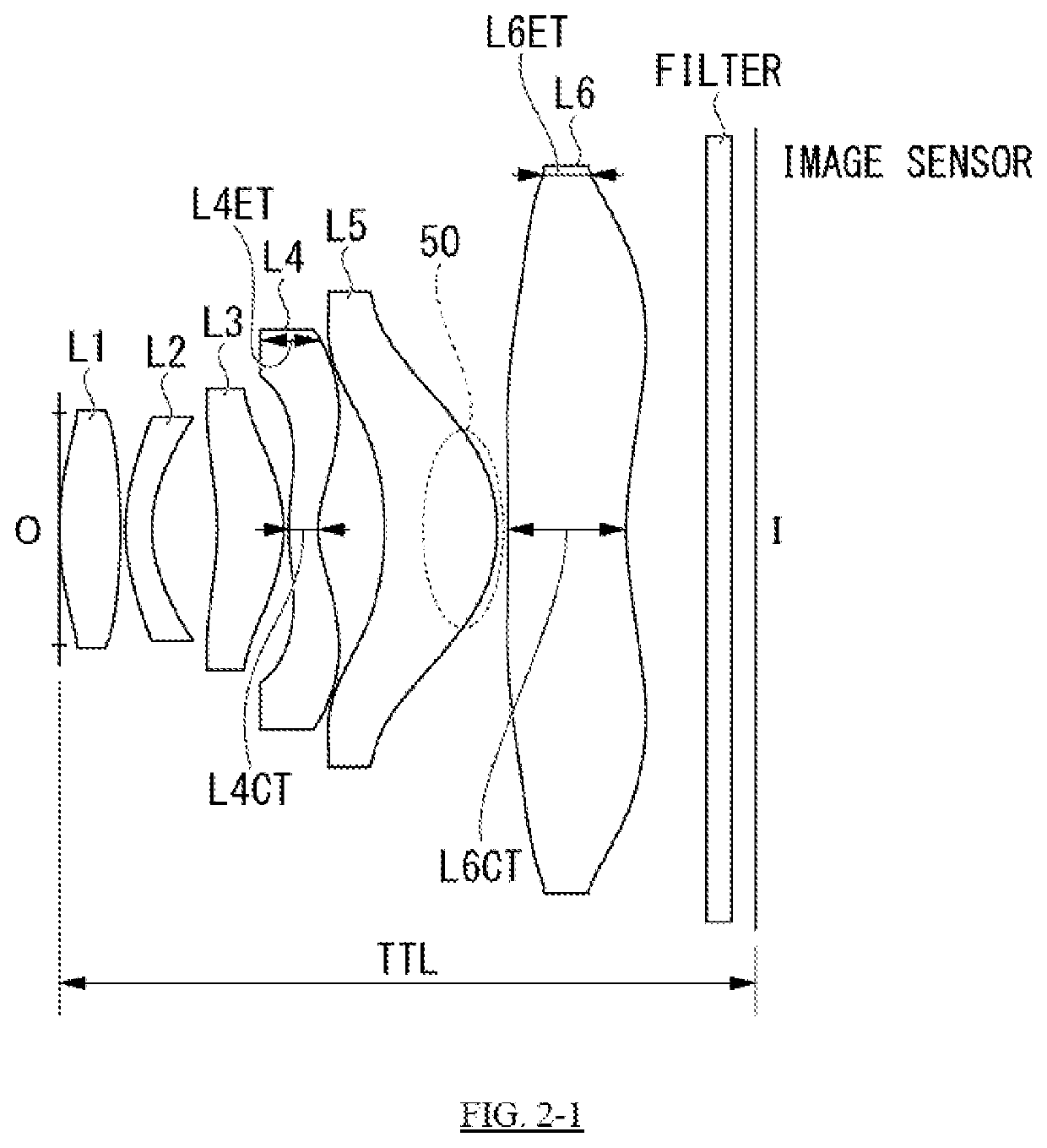
[0056]FIG. 2-1 shows a cross-sectional illustration of a second embodiment of a six-piece optical lens system. FIG. 2-1 also shows a filter in front of an image sensor surface I.
[0057]In the second embodiment, the six-piece optical lens system comprises elements same as the First embodiment, providing TTL which is longer than that of the first embodiment.
[0058]Table 2-1 shows the radius of curvature (r) and the thickness or separation (d) for each of the optical surfaces, and refractive index (N) and the Abbe number (v) for each of the lens elements of the six-piece optical lens system of the second embodiment.
TABLE 2-1RefractiveAbbeSurfaceRadiusThicknessIndex(N)Number(v)StopInfinity0——L1R12.5900.5071.5456.0R2−4.5470.040L2R11.5480.2201.6719.2R21.0120.548L3R1−2.9610.5571.5456.0R2−1.1580.040L4R11.4240.2461.5737.4R20.6990.553L5R1−4.7510.9371.5455.6R2−2.2120.090L6R13.4470.9941.5455.6R23.4380.670IRCFR1Infinity0.2101.5264.2R2Infinity0.200SensorInfinity0.000——
[0059]Table 2-2 shows the asph...
third embodiment
[0063]FIG. 3-1 shows a cross-sectional illustration of a third embodiment of a six-piece optical lens system. FIG. 3-1 also shows a filter in front of an image sensor surface I.
[0064]In the third embodiment, the six-piece optical lens system comprises elements same as the First embodiment, providing F number which is smaller than that of the first embodiment.
[0065]Table 3-1 shows the radius of curvature (r) and the thickness or separation (d) for each of the optical surfaces, and refractive index (N) and the Abbe number (v) for each of the lens elements of the six-piece optical lens system of the third embodiment.
TABLE 3-1RefractiveAbbeSurfaceRadiusThicknessIndex(N)Number(v)StopInfinity0——L1R12.5860.3221.5456.0R2−2.7330.030L2R11.1560.2001.6719.2R20.7340.370L3R1−5.0510.4571.5456.0R2−0.7970.030L4R13.5950.2601.5737.4R20.5520.336L5R14.8830.8391.5455.6R2−1.6020.067L6R12.3980.6851.5455.6R22.4730.340IRCFR1Infinity0.2101.5264.2R2Infinity0.200SensorInfinity0.000——
[0066]Table 3-2 shows the as...
PUM
 Abstract
Description
Claims
Application Information
 - R&D
- Intellectual Property
- Life Sciences
- Materials
- Tech Scout
- Unparalleled Data Quality
- Higher Quality Content
- 60% Fewer Hallucinations
Browse by: Latest US Patents, China's latest patents, Technical Efficacy Thesaurus, Application Domain, Technology Topic, Popular Technical Reports.
© 2025 PatSnap. All rights reserved.Legal|Privacy policy|Modern Slavery Act Transparency Statement|Sitemap|About US| Contact US: help@patsnap.com