
Manifold assembly

a manifold and assembly technology, applied in the direction of manure treatment, liquid fertiliser regulation system, sludge spreader, etc., can solve the problems of manure flowing, overall reduction in total yield, light growth bump, etc., and achieve rapid/easily adjusted, high flow rate, and high flow rate

Pending Publication Date: 2022-09-22
AG PREMIER INC
View PDF0 Cites 0 Cited by
  • Summary
  • Abstract
  • Description
  • Claims
  • Application Information

AI Technical Summary

Benefits of technology

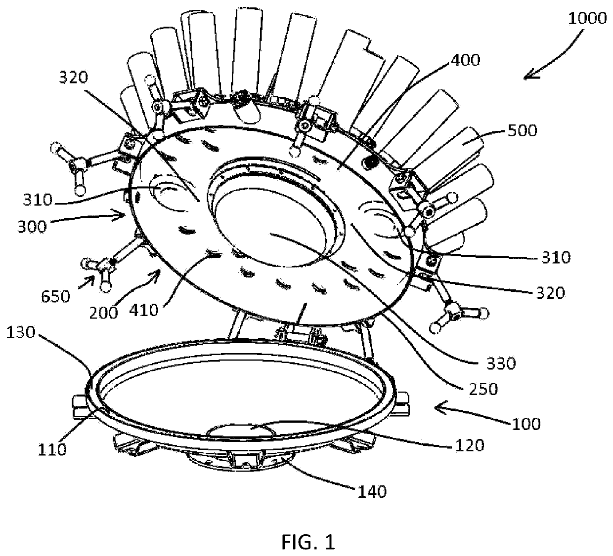
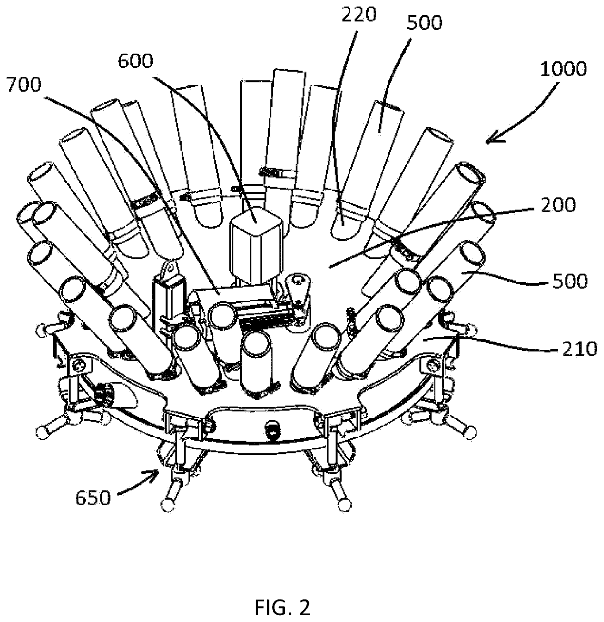
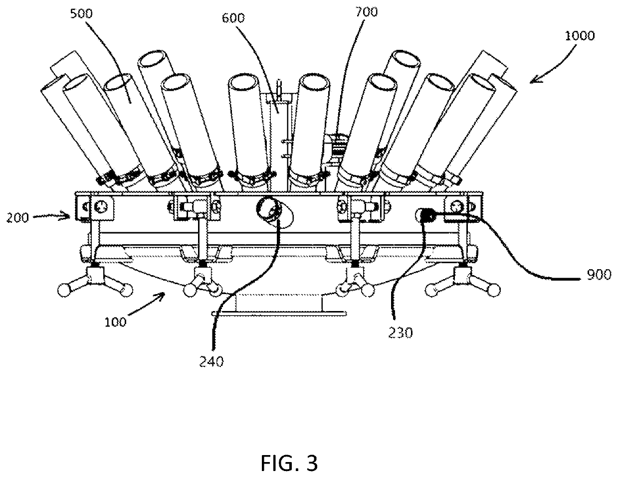
The invention is a new manifold designed to reduce problems with high flow rates and limited adjustability. The manifold can be easily adjusted for lower flow rates and low internal pressures to maintain even flow across a wide range of flow rates. An electric pressure transducer can detect pressure in the manifold and send a signal to a digital readout in the tractor cab, allowing for real-time adjustment. The manifold plate can be rotated with an electric actuator to open and restrict each port out of the manifold to maintain a desired pressure in the manifold. This feature helps to keep the flow equal to each port and maintain even flow across a wide range of flow rates. The patent text describes a new tool that allows operators to maintain even nutrient application for the next crop.

Problems solved by technology

Crops that get too much manure might have a slight bump in growth and yield but the crops having too little manure are stunted which causes an overall reduction in total yield.
Low internal pressure may result in manure flowing out of only a few ports in the manifold while other ports have little or no flow of liquid manure.
A problem, however, is that manifolds designed for even flow at high gallons per minute perform poorly when the flow is relatively low.
This may happen when: 1) manure becomes thick as the pit level is lowered; 2) a low application rate is required (gallons / acre), and 3) the operator cannot pull the toolbar fast enough to keep the gallons per minute up.
However, as the pit level drops to the last couple feet, the manure can become so thick that the operator might only be able to pump 900-1,000 GPM.
At these lower flow rates a manifold designed for 2500 GPM will not perform well.
In this case, the toolbar and hose can only be pulled so fast so at the hog facility they are forced to slow their flow down to 1,800 gallons per minute and cause the manifold not to perform as required.
Trash in the manure is also a problem in that it may cause a manifold to plug.
As the pit level lowers and the manure becomes thicker the manifold may drop to say 2 PSI, without any adjustments this causes the flow to become very uneven.

Method used


Image

  • Manifold assembly
  • Manifold assembly
  • Manifold assembly

Examples


Embodiment Construction

[0024]Example embodiments will now be described more fully with reference to the accompanying drawings, in which example embodiments of the invention are shown. The invention may, however, be embodied in different forms and should not be construed as limited to the embodiments set forth herein. Rather, these embodiments are provided so that this disclosure will be thorough and complete, and will fully convey the scope of the invention to those skilled in the art. In the drawings, the sizes of components may be exaggerated for clarity.

[0025]It will be understood that when an element or layer is referred to as being “on,”“connected to,” or “coupled to” another element or layer, it can be directly on, connected to, or coupled to the other element or layer or intervening elements or layers that may be present. In contrast, when an element is referred to as being “directly on,”“directly connected to,” or “directly coupled to” another element or layer, there are no intervening elements or...


PUM


Abstract

Disclosed is a nonlimiting example of a manifold assembly. In example embodiments the manifold assembly may include a manifold bowl, a manifold cover over the manifold bowl, a manifold plate having a plurality of holes, a restraint structure configured to prevent the manifold plate from translating and overturning, and an actuator configured to rotate the manifold plate. In one nonlimiting example embodiment the manifold cover has a plurality of holes and a plurality of hose barbs aligned with the plurality of holes. In this nonlimiting example embodiment the plurality of holes in the manifold plate are alignable with the plurality of holes in the manifold cover. In at least one nonlimiting example embodiment, rotating the manifold plate aligns and misaligns the holes in the manifold plate and the holes in the manifold cover.

Description

CROSS-REFERENCE TO RELATED APPLICATIONS[0001]This application claims the benefit of U.S. Provisional Patent Application No. 63 / 162,668 which was filed with United States Patent and Trademark Office on Mar. 18, 2021, the entire contents of which are herein incorporated by reference.BACKGROUND1. Field[0002]Example embodiments relate to a manifold assembly. In one nonlimiting example embodiment, the manifold assembly may be used as part of a liquid manure application system.2. Description of the Related Art[0003]Liquid manure systems use manifolds to distribute liquid manure to various row units. Generally speaking, the manure runs from a manifold to the row units via a plurality of hoses. Ideally, manifolds distribute manure through each hose evenly to promote an even application of manure to the ground. When flow is not even, some crops receive too much manure while other crops receive too little. Crops that get too much manure might have a slight bump in growth and yield but the cro...

Claims


Application Information

Patent Timeline
Patent Type & Authority Applications(United States)
IPC IPC(8): A01C23/00F16L41/03
CPCA01C23/002F16L41/03A01C23/007
Inventor ZOSKE, MICK
Owner AG PREMIER INC
Learn More