Pressure control mechanism for fireguns

Pending Publication Date: 2022-09-22
TASYAGAN BAHTIYAR
View PDF0 Cites 0 Cited by
  • Summary
  • Abstract
  • Description
  • Claims
  • Application Information

AI Technical Summary

Benefits of technology

The present invention is about a structure for a firearm that allows for safe and proper firing of different types of ammunitions without making any changes to the firearm assembly. The structure also ensures that the ammunition is moved to the firing position without disrupting the line of firing position. Additionally, the invention provides a pressure control structure that is cost-efficient and user-friendly, and allows for adjusting the pressure of the gas reaching the piston during firing. The pressure control structure utilizes a single-piston and allows for proper operation of the firearm regardless of the ammunition type. The bolt handle of the firearm includes a gas chamber lug and a bolt handlebar that can position the bolt handle. The bolt handle also has a ball setscrew hole for attaching a battery.

Problems solved by technology

However, when a type of ammunition that is suitable for heavy arms (magnum) is desired to be used in firearms formed in such manner, the gas piston moves with breakneck speed as the amount of the gunpowder charge is much higher, thereby causing damage to the rifle mechanism as well as the assembly thereof.
Using both small and heavy (magnum) arms ammunition in the same firearm poses serious problems.
The firearm fails to offer the same efficiency in both cases.
This particular difference causes various problems when ammunition types with different fillings are desired to be used in the same firearm.
When using a type of ammunition that is suitable for small arms, the firearm cannot be cocked again after firing, and when using a type of ammunition that is suitable for heavy arms, the mechanism, as well as the assembly of the firearm, may sustain damage.
In this application, however, additional costs incur as the user is required to purchase a second gas piston.
This causes difficulty of use for the user every time the user wishes to change the ammunition type.
Moreover, losing the additional gas piston for different types of ammunition is also among the frequently encountered problems.
Quite naturally, this brings additional costs for the user.
Furthermore, since said valve is positioned on the barrel portion of the firearm, it disrupts the stance of the user, i.e. the line of firing position gets interrupted, thereby inducing difficulty of use.
This is, of course, an undesired result for the user.
Moreover, the system formed together with a valve, requires frequent maintenance.
In case periodical maintenance gets disrupted or not performed regularly, the system may stop working properly and become dysfunctional.
Although these systems which comprise regulators, provide a viable solution for small firearms, they cause major problems in heavier firearms utilizing magnum ammunition.
However, adjusting the system with regulator falls behind the instant involving the re-cocking of the firearm under high pressure.
Therefore, such systems are not recommended for being used with magnum ammunitions.

Method used


Image

  • Pressure control mechanism for fireguns
  • Pressure control mechanism for fireguns
  • Pressure control mechanism for fireguns

Examples


Embodiment Construction

[0023]To be able to understand the novelties brought forth for the purpose of achieving the aforementioned objects, the inventive gas pressure control structure needs to be evaluated in consideration of the figures disclosed below, wherein;

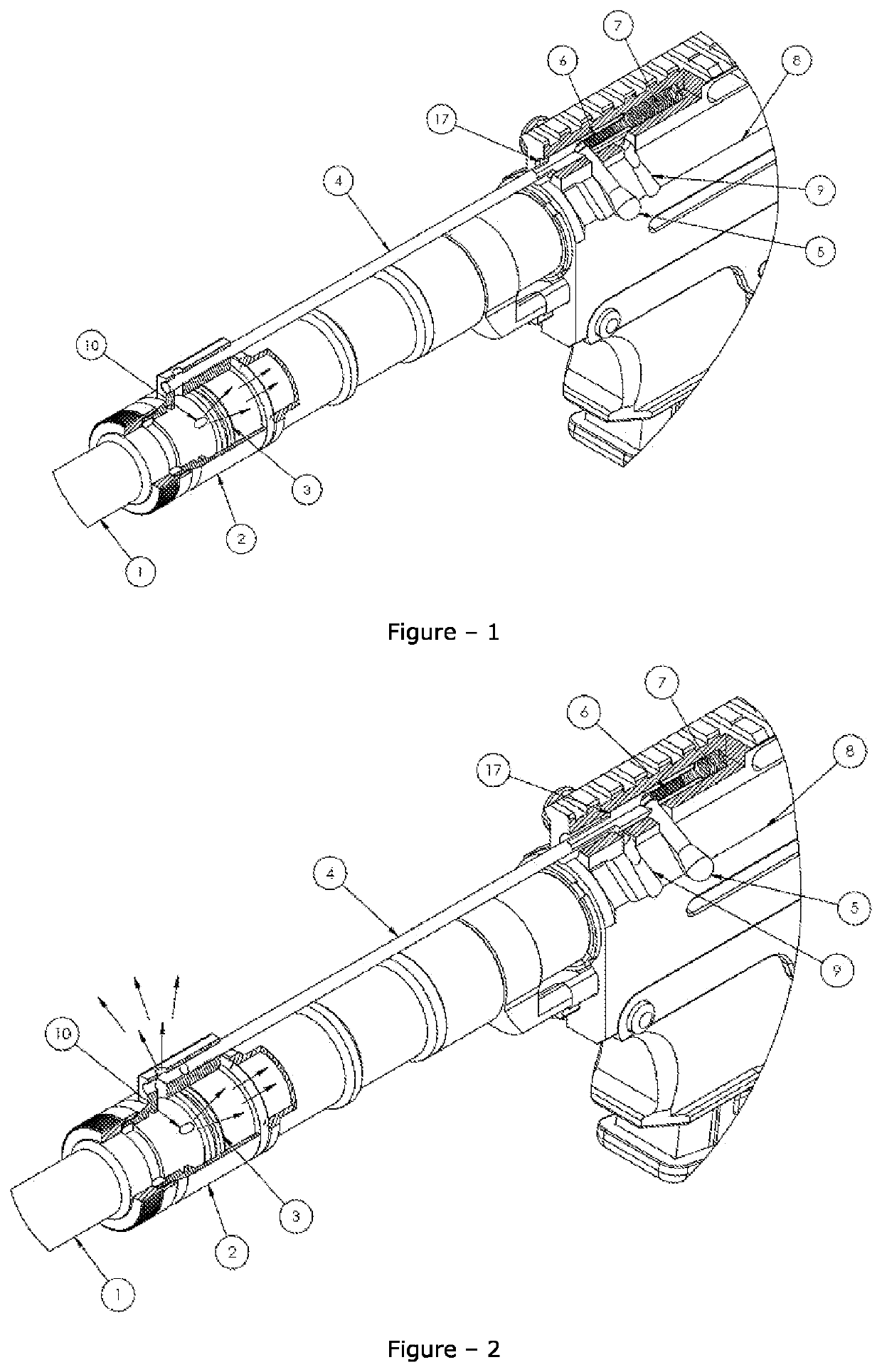
[0024]FIG. 1 illustrates the drawing in which the gas discharge port (exhaust) is shut by the bolt handle in the system installed to a firearm suitable for firing ammunition for small arms.

[0025]FIG. 2 illustrates the drawing in which the gas discharge port (exhaust) is open in the system installed to a firearm suitable for firing ammunition for heavy arms (magnum).

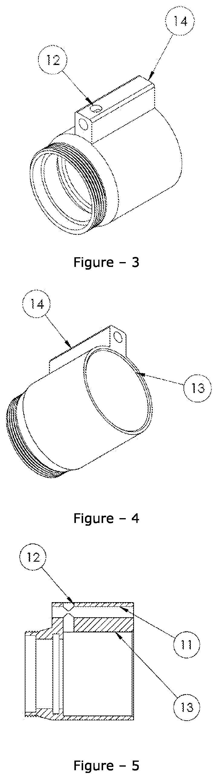
[0026]FIG. 3 illustrates the front perspective view of the gas chamber which is the first element of the inventive structure.

[0027]FIG. 4 illustrates the rear perspective view of the gas chamber which is the first element of the inventive structure.

[0028]FIG. 5 illustrates the sectional view of the gas chamber which is the first element of the inventive structure.

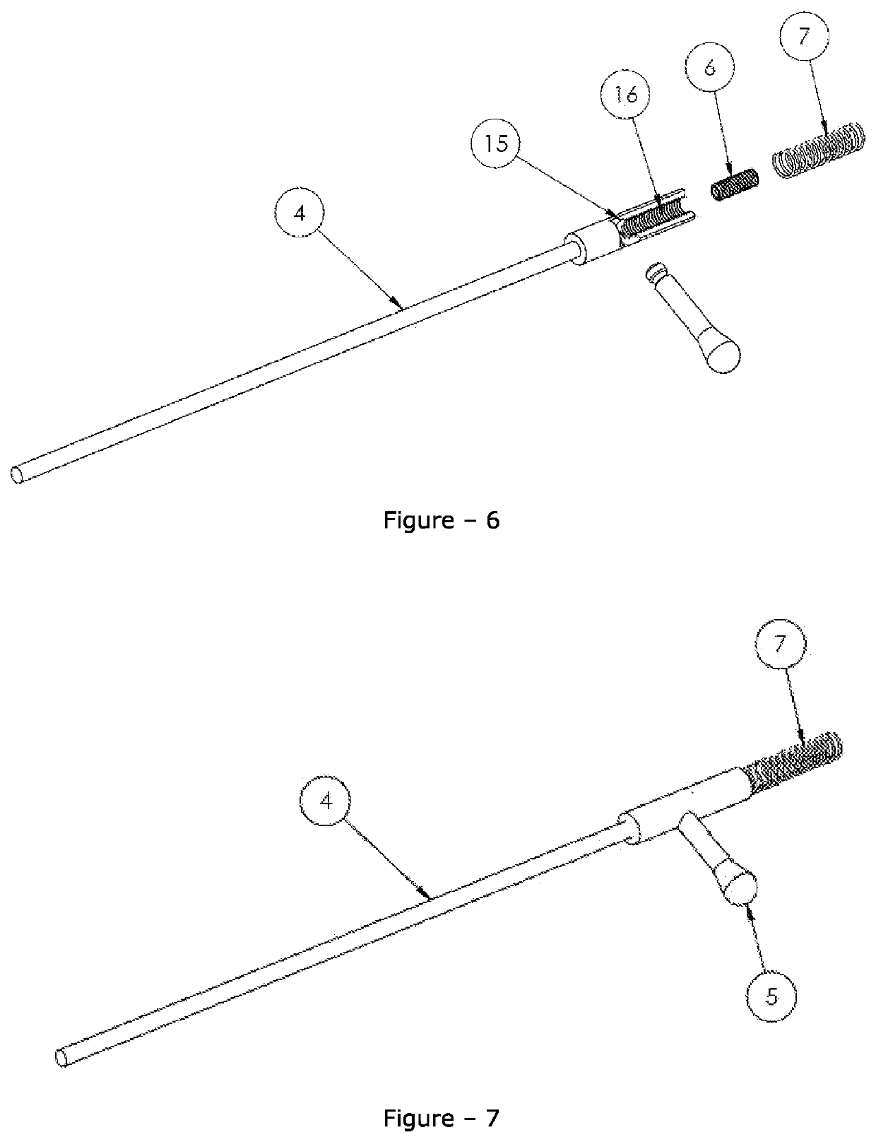
[0029]FIG. 6 illustrate...


PUM


Abstract

The present invention relates to a pressure control structure that is developed to be used in semi-automatic firearms operating with gas pressure, that allows for using any type of live ammunition (small / magnum) easily by maintaining the stability of the gas pressure created as a result of firing the firearm and enables cocking the rifle mechanism, that protects the parts of the rifle as well as the assembly thereof and that provides the user a more comfortable firing experience.

Description

TECHNICAL FIELD OF THE INVENTION[0001]The present invention relates to a pressure control structure that is developed to be used in semi- automatic firearms operating with gas pressure, that allows for using any type of live ammunition (small / magnum) easily by maintaining the stability of the gas pressure created as a result of firing the firearm and enables cocking the rifle mechanism, that protects the parts of the rifle as well as the assembly thereof and that provides the user a more comfortable firing experience.PRIOR ART[0002]Nowadays, many different ammunition types of various grammage and structure are utilized in semi-automatic firearms. Considering the operation principle of a firearm used in the state of the art, the ammunition is fed into the chamber and fired via the firearm muzzle, thereby creating a gas pressure upon the burning of the gunpowder contained therein. The gas generated therein allows for firing the bullet inside the ammunition through the barrel of the fi...

Claims


Application Information

Patent Timeline
IPC IPC(8): F41A5/28
CPCF41A5/28
Inventor TASYAGAN, BAHTIYAR
Owner TASYAGAN BAHTIYAR
Why Eureka
Try Eureka