Depth processor

a processor and depth technology, applied in the field of processors, can solve the problems of consuming a lot of operational time, power consumption and/or transmission bandwidth of a depth processor, and achieve the effect of reducing operational time, power consumption and/or transmission bandwidth

Active Publication Date: 2022-09-22
HIMAX TECH LTD
View PDF3 Cites 0 Cited by
  • Summary
  • Abstract
  • Description
  • Claims
  • Application Information

AI Technical Summary

Benefits of technology

[0004]The invention is directed to a depth processor, wherein operational time, power consumption and / or transmission bandwidth can be reduced since only a region of interest (ROI) is processed to obtain a depth map of the region of interest.

Problems solved by technology

However, it may take a lot of operational time, power consumption and / or transmission bandwidth of a depth processor for calculating and generating a depth map of a whole input image.

Method used


Image

  • Depth processor
  • Depth processor

Examples


Embodiment Construction

[0016]Reference will now be made in detail to the present preferred embodiments of the invention, examples of which are illustrated in the accompanying drawings. Wherever possible, the same reference numbers are used in the drawings and the description to refer to the same or like parts.

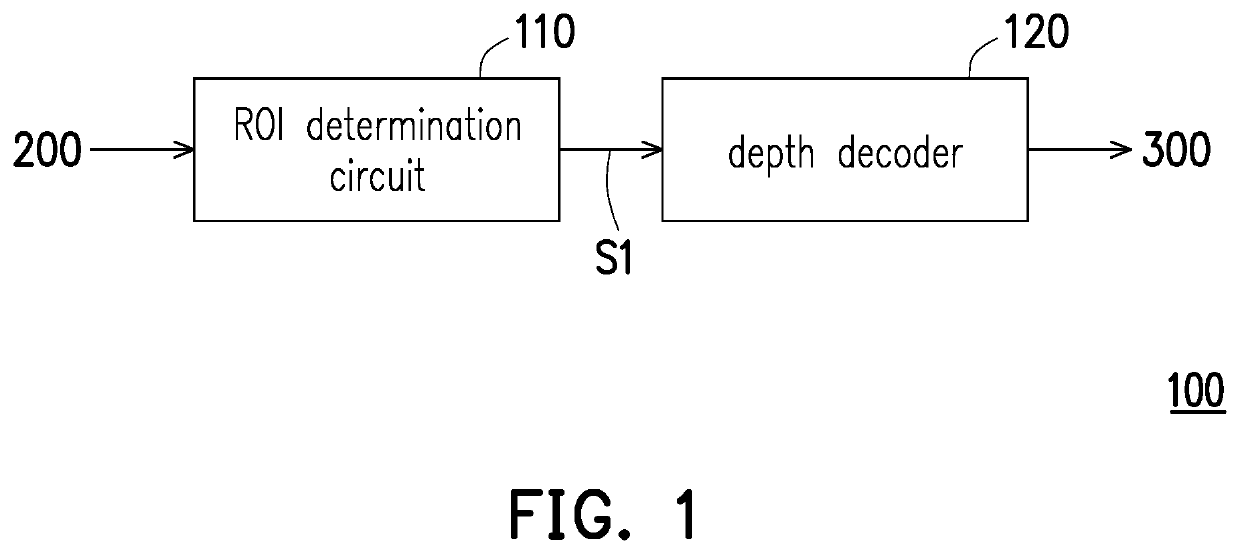
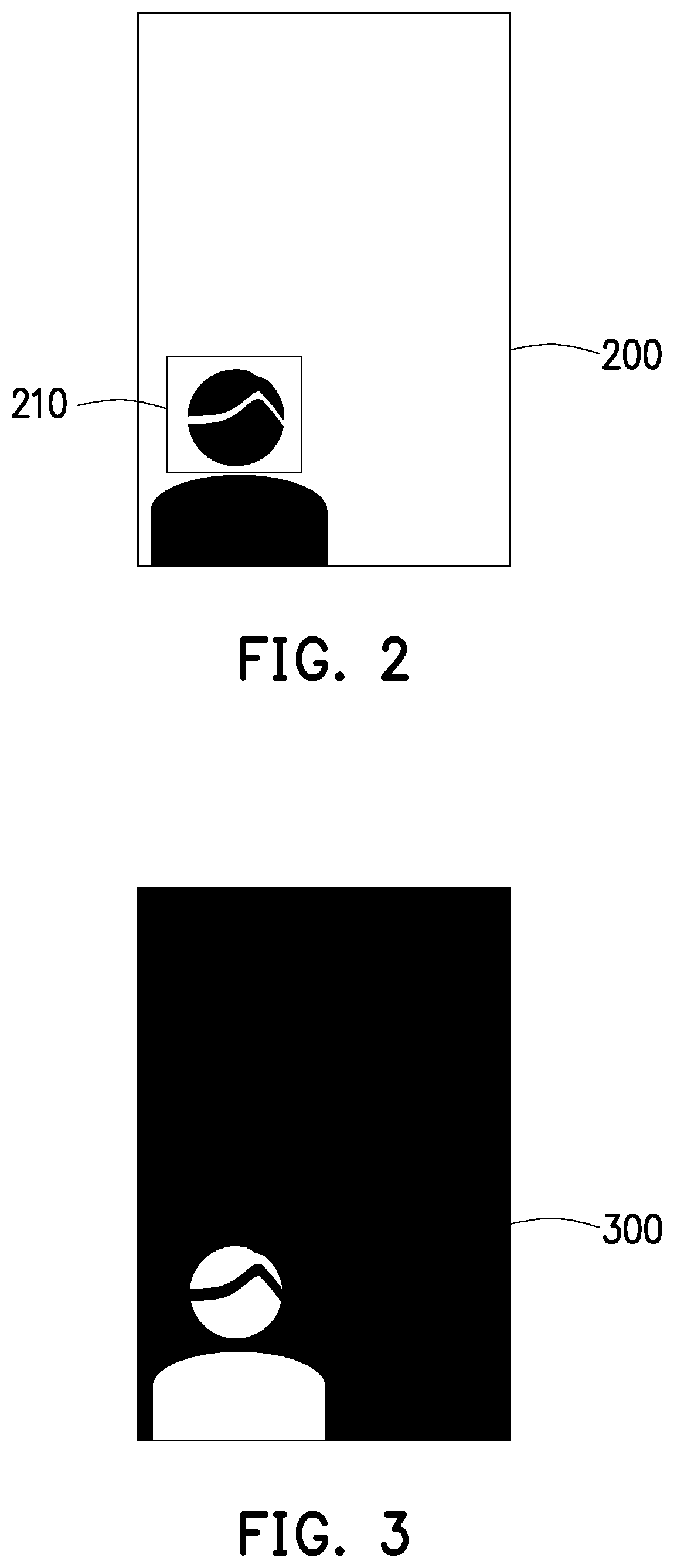
[0017]FIG. 1 is a block diagram illustrating a depth processor according to an embodiment of the invention. FIG. 2 is a schematic diagram illustrating an input image of FIG. 1 according to an embodiment of the invention. FIG. 3 is a schematic diagram illustrating a depth map of FIG. 1 according to an embodiment of the invention.

[0018]Referring to FIG. 1 and FIG. 2, the depth processor 100 is configured to receive the input image 200 from a camera and output the depth map 300 to a back-end system for facial recognition. In the present embodiment, the input image 200 is a two-dimensional image. The depth processor 100 includes a region of interest (ROI) determination circuit 110 and a depth decoder 120...


PUM


Abstract

A depth processor including a region of interest determination circuit and a depth decoder is provided. The region of interest determination circuit is configured to determine a region of interest of an input image. The depth decoder is coupled to the region of interest determination circuit and configured to generate a depth map of the region of interest of the input image.

Description

BACKGROUNDTechnical Field[0001]The invention relates to a processor, more specifically, to a depth processor.Description of Related Art[0002]As an application of facial recognition system develops, various sensors for detecting three-dimensional images of faces are flourishing. Taking a structured light technology for example, structured lights are projected to an object by using a projector, and sensors detect a projection image. Therefore, a triangle geometry structure among the object, the projector and the sensors can be obtained, and further a depth map can be generated according to the triangle geometry structure and a deformation displacement of the projection image. In addition, time of flight or phase difference of an output light and a receiving light is also widely applied to the facial recognition system to calculate the depth map.[0003]However, it may take a lot of operational time, power consumption and / or transmission bandwidth of a depth processor for calculating and...

Claims


Application Information

Patent Timeline
Patent Type & Authority Applications(United States)
IPC IPC(8): G06T7/50G06K9/00
CPCG06T7/50G06K9/00228G06T2207/30201G06T2207/10024G06V10/25G06V40/161
Inventor LU, HSUEH-TSUNGWANG, CHING-WENTSAI, CHENG-CHECHEN, WU-FENG
Owner HIMAX TECH LTD
Why Eureka
Try Eureka