Parallel charger circuit with battery feedback control

a parallel charger and feedback control technology, applied in battery overheating protection, safety/protection circuits, transportation and packaging, etc., can solve the problems of introducing one or more disadvantages, and affecting the operation of parallel chargers. the effect of reducing latency and smoothing out the amount of power provided

Pending Publication Date: 2022-09-22
GOOGLE LLC
View PDF0 Cites 0 Cited by
  • Summary
  • Abstract
  • Description
  • Claims
  • Application Information

AI Technical Summary

Benefits of technology

[0003]In accordance with one or more techniques of this disclosure, a device may include a regulated parallel charger and a controller that regulates operation of the parallel charger based on an amount of cur...

Problems solved by technology

However, such a scheme may present one or more disadvantages.
As one example, communicating with the external power source may introduce latency.
As another example, the input current of the parallel charger may not be an accurate representation of how much current is actually being provided to the one or ...

Method used


Image

  • Parallel charger circuit with battery feedback control
  • Parallel charger circuit with battery feedback control
  • Parallel charger circuit with battery feedback control

Examples


example 1

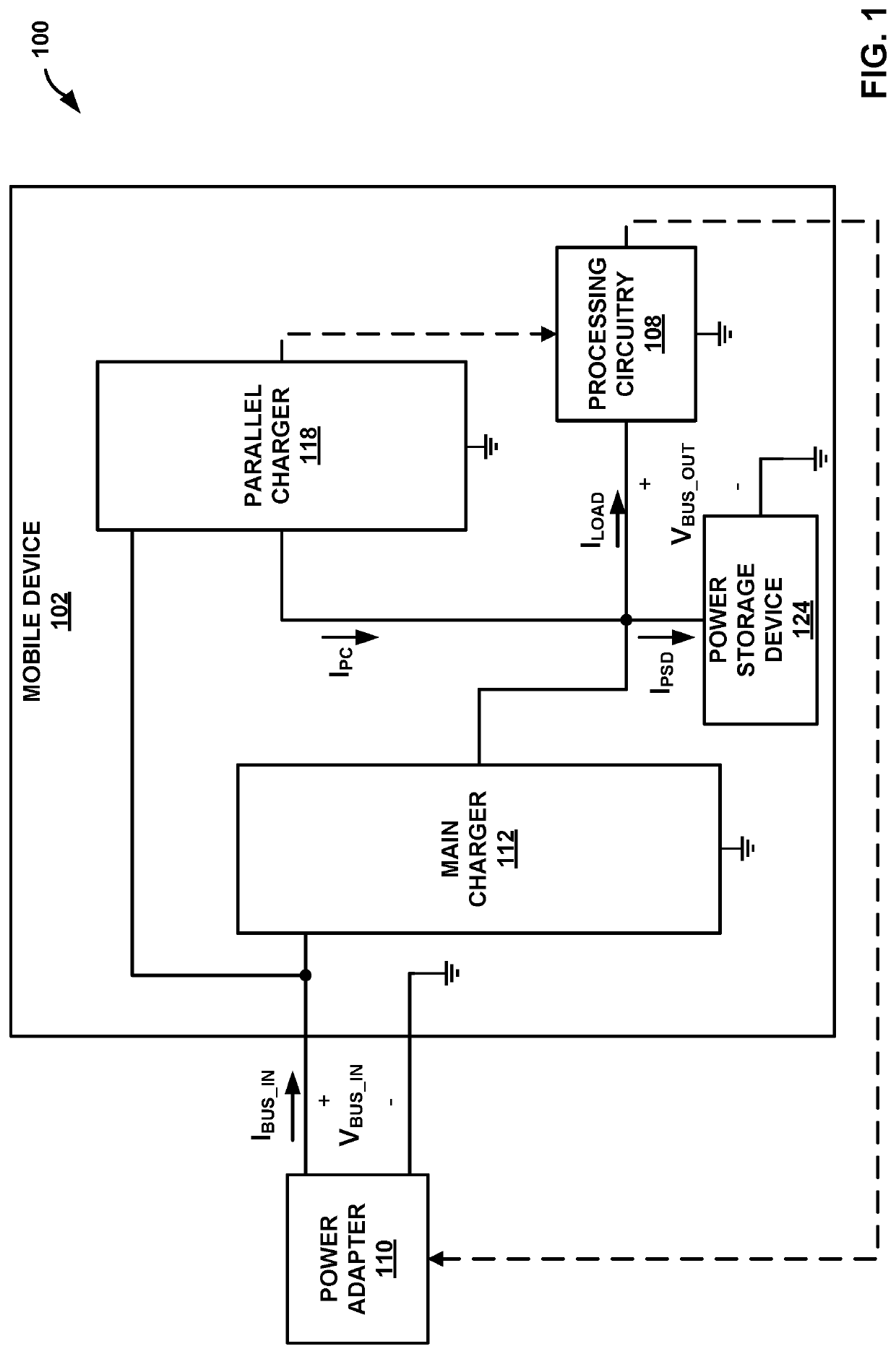
[0058] A device comprising: a power storage device; an electrical load; a first regulated power converter including components configured to generate, during a first time period and using electrical energy received from a power source external to the device, a first power signal to charge the power storage device; and a second regulated power converter including components configured to: determine a charging current at which to charge the power storage device; determine a total amount of current flowing to the power storage device that includes current sourced by the second regulated power converter less current sinked by the electrical load; and generate, during a second time period that is non-overlapping with the first time period, using electrical energy received from the power source and based on the determined total amount of current, a second power signal to charge the power storage device at the determined charging current.

example 2

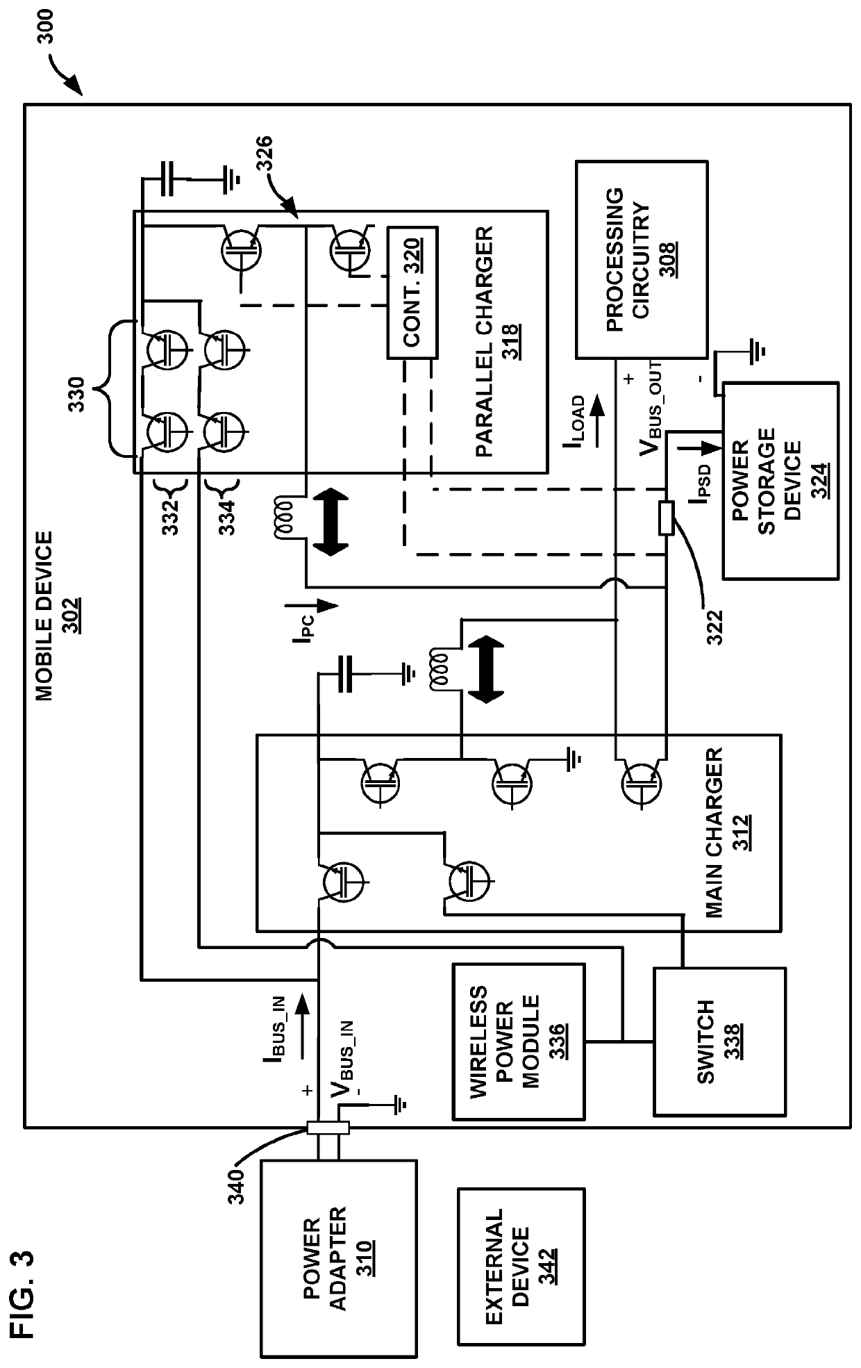
[0059] The device of example 1, wherein the second regulated power converter comprises a bi-directional regulated power converter, wherein the components of the bi-directional regulated power converter are further configured to generate, during a third time period that is non-overlapping with the second time period and using electrical energy sourced from the power storage device, a third power signal to power an external device that is coupled to the device.

example 3

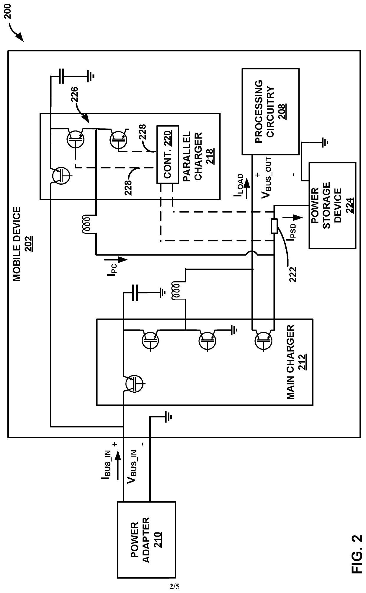
[0060] The device of example 1 or 2, wherein the second regulated power converter further comprises: a buck converter configured to generate, using the electrical energy received from the power source, the second power signal to charge the power storage device; and a controller electrically coupled to the buck converter that controls a duty cycle of the buck converter based on the determined total amount of current such that the buck converter generates the second power signal with an amount of current equal to the determined charging current and the current sinked by the electrical load.

[0061]Example 4. The device of example 3, further comprising a current sensor configured to generate a signal that represents the total amount of current flowing to the power storage device, wherein the controller is configured to determine the total amount of current flowing to the power storage device based on the signal generated by the current sensor.

[0062]Example 5. The device of example 3 or 4...


PUM


Abstract

In general, techniques are described that are directed to a device that includes a power storage device, an electrical load, and a first regulated power converter including components configured to generate, during a first time period and using electrical energy received from a power source external to the device, a first power signal to charge the power storage device. A second regulated power converter includes components configured to determine a charging current at which to charge the power storage device, determine a total amount of current flowing to the power storage device that includes current sourced by the second power converter less current sinked by the electrical load, and generate, during a second time period that is non-overlapping with the first time period, using electrical energy from the power source and based on determined the total amount of current, a second power signal to charge the power storage device.

Description

BACKGROUND[0001]A device may include multiple on-board chargers that are each capable of charging one or more power sources (e.g., batteries) of the device using power received from an external source. The on-board chargers may include a main charger and a parallel charger, each with different characteristics. Depending on charging context, a controller of the device may utilize the main charger or the parallel charger to charge the one or more power sources using the power received from the external source.BRIEF SUMMARY[0002]In general, this disclosure is directed to devices that include dual on-board regulated chargers. A controller of a device with a regulated main charger and an unregulated parallel charger may regulate an amount of power provided by the unregulated parallel charger by adjusting an amount of power provided by an external power source that is supplying power to the device. For example, the controller may measure an input current of the parallel charger and output...

Claims


Application Information

Patent Timeline
IPC IPC(8): H02J7/00H02J7/34
CPCH02J7/00716H02J7/00308H02J7/342H02J1/109H02M3/1584H02J7/00309H02J7/34H02M3/156
Inventor FEI, CHAOOSTERHOUT, DOUGLASLAKSHMIKANTHAN, SRIKANTHJIA, LIANGWANG, LI
Owner GOOGLE LLC
Why Eureka
Try Eureka