Electrochemical hydrogen compressor

a hydrogen compressor and electrochemical technology, applied in the field of electrochemical hydrogen compressors, can solve the problems of excessively high the tendency of the electrolyte membrane to dry, and achieve the effect of preventing the temperature of the electrolyte membrane from becoming excessively high, preventing the electrolyte membrane from drying, and increasing the amount of evaporation (water vapor)

Active Publication Date: 2022-09-29
HONDA MOTOR CO LTD
View PDF1 Cites 1 Cited by
  • Summary
  • Abstract
  • Description
  • Claims
  • Application Information

AI Technical Summary

Benefits of technology

[0007]An electrochemical hydrogen compressor comprising an electrochemical cell including a membrane electrode assembly including an electrolyte membrane capable of conducting a hydrogen ion, and an anode electrode and a cathode electrode sandwiching the electrolyte membrane, and an anode separator and a cathode separator arranged on both sides of the membrane electrode assembly, wherein hydrogen gas supplied to the anode electrode is pressurized electrochemically to generate at the cathode electrode hydrogen gas having a higher pressure than the hydrogen gas, the electrochemical cell including: a first flow field member that is located between the anode electrode and the anode separator and includes a hydrogen gas flow field that guides the hydrogen gas to the anode electrode; a second flow field member that is located between the anode electrode and the first flow field member and includes a water channel through which liquid water for humidifying the hydrogen gas and cooling the electrolyte membrane flows; a first porous member that is located between the first flow field member and the second flow field member; and a second porous member that is located between the second flow field member and the anode electrode, wherein the first porous member permits flow of the hydrogen gas from the hydrogen gas flow field to the water channel and prevents flow of the liquid water, and wherein the second porous member permits flow of the hydrogen gas and water vapor from the water channel and prevents flow of the liquid water.
[0008]According to the present invention, the hydrogen gas supplied to the hydrogen gas flow field of the electrochemical cell is carried into the water channel through the first porous member and humidified by liquid water flowing through the water channel. The humidified hydrogen gas (hydrogen gas containing water vapor) is led to the anode electrode through the second porous member and humidifies the electrolyte membrane. That is, the hydrogen gas is humidified inside the electrochemical cell. Therefore, it is possible to suppress drying of the electrolyte membrane caused by condensation (lack of moisture) in the pipe arranged outside the electrochemical hydrogen compressor.
[0009]In addition, the electrolyte membrane generating heat during operation of the electrochemical cell can be cooled by liquid water of the water channel. Therefore, it is possible to prevent the temperature of the electrolyte membrane from becoming excessively high and the electrolyte membrane from drying. Further, as the temperature of the electrolyte membrane increases, the temperature of the liquid water increases and the amount of evaporation (amount of water vapor) increases. Thus, it is possible to effectively suppress drying of the electrolyte membrane.

Problems solved by technology

However, when water in the hydrogen gas flowing through the pipe is condensed on the pipe, the electrolyte membrane tends to dry.

Method used


Image

  • Electrochemical hydrogen compressor
  • Electrochemical hydrogen compressor
  • Electrochemical hydrogen compressor

Examples


Embodiment Construction

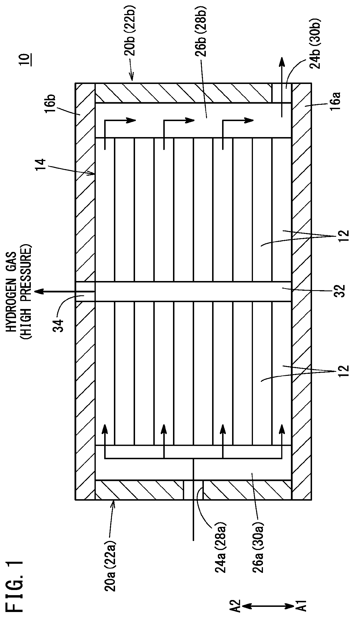
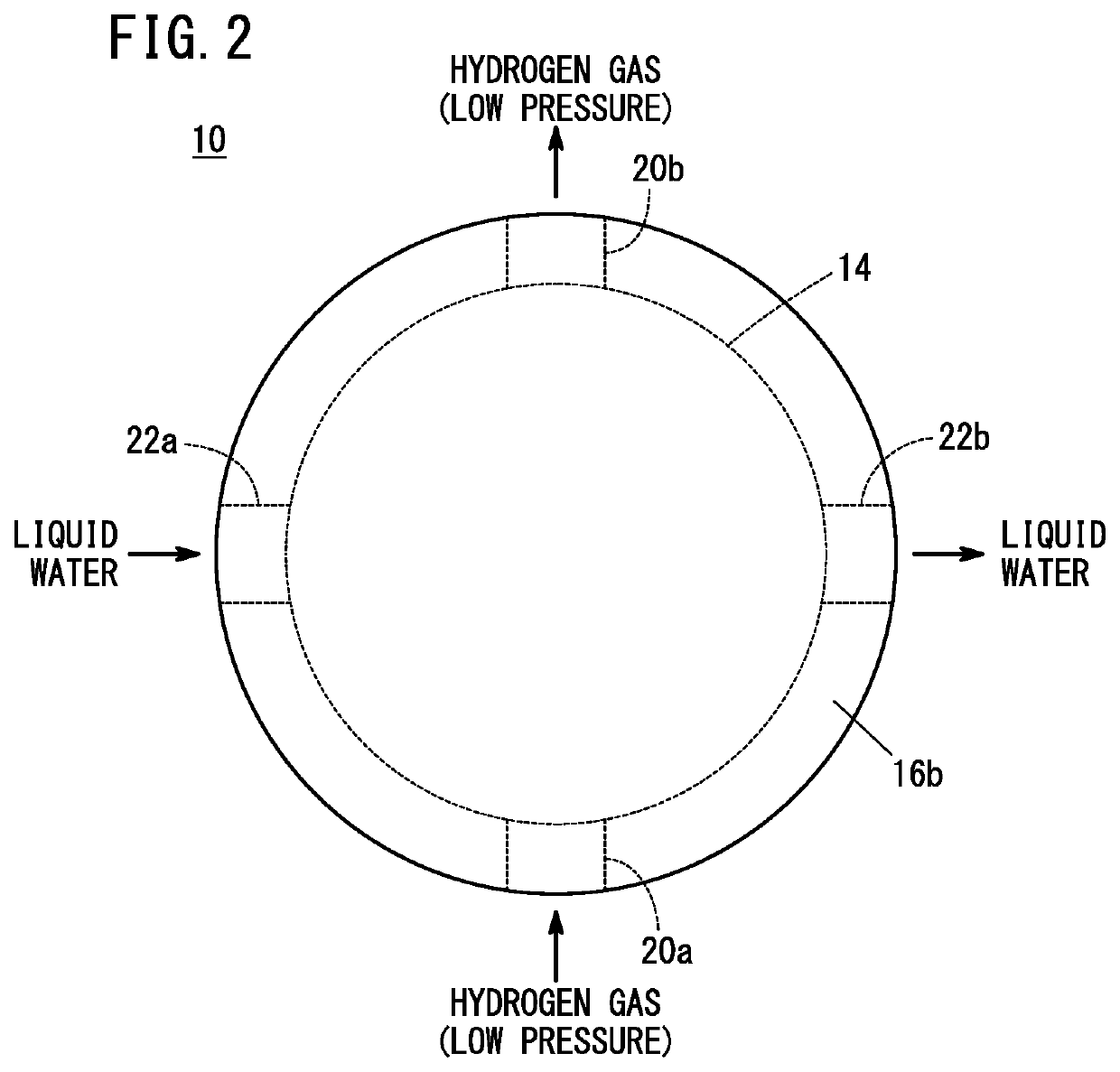
[0015]As shown in FIGS. 1 and 2, an electrochemical hydrogen compressor 10 according to an embodiment of the present invention is a booster that electrochemically boosts low-pressure hydrogen gas supplied from a hydrogen tank or the like (not shown) via an external pipe to high-pressure hydrogen gas.

[0016]An electrochemical hydrogen compressor 10 includes a cell stack 14, a first end plate 16a, and a second end plate 16b. In the cell stack 14, a plurality of electrochemical cells 12 are stacked in the thickness direction. The first end plate 16a is located at one end of the cell stack 14. The second end plate 16b is located at the other end of the cell stack 14. The first end plate 16a and the second end plate 16b are fastened by a plurality of bolts (not shown). Thus, a clamping load is applied to the cell stack 14 by the first end plate 16a and the second end plate 16b. A power supply device (not shown) for supplying electricity to each electrochemical cell 12 is connected to the ...


PUM

PropertyMeasurementUnit
pressureaaaaaaaaaa
water repellencyaaaaaaaaaa
thicknessaaaaaaaaaa

Abstract

An electrochemical cell of an electrochemical hydrogen compressor is provided with a first flow field member having a hydrogen gas flow field and a second flow field member having a water channel. The first flow field member is located between the anode electrode and the anode separator. The second flow field member is located between the anode electrode and the first flow field member. A first porous member is located between the first flow field member and the second flow field member. A second porous member is located between the second flow field member and the anode electrode.

Description

CROSS-REFERENCE TO RELATED APPLICATIONS[0001]This application is based upon and claims the benefit of priority from Japanese Patent Application No. 2021-054523 filed on Mar. 29, 2021, the contents of which are incorporated herein by reference.BACKGROUND OF THE INVENTIONField of the Invention[0002]The present invention relates to an electrochemical hydrogen compressor.Description of the Related Art[0003]For example, JP 2016-089220 A discloses a differential pressure type high-pressure water electrolysis apparatus that electrolyzes water and generates high-pressure hydrogen. The differential pressure type high-pressure water electrolysis apparatus includes an electrochemical cell. The electrochemical cell has a membrane electrode assembly, an anode separator, and a cathode separator. The membrane electrode assembly includes an electrolyte membrane, an anode electrode disposed on one surface of the electrolyte membrane, and a cathode electrode disposed on the other surface of the elect...

Claims


Application Information

Patent Timeline
Patent Type & Authority Applications(United States)
IPC IPC(8): C25B1/04C25B9/19C25B13/08C25B9/60
CPCC25B1/04C25B9/19C25B13/08C25B9/60C25B11/02C25B1/042Y02E60/50C25B1/02C25B9/23Y02E60/36
Inventor TAKASUGI, SHOJI
Owner HONDA MOTOR CO LTD
Why Eureka
Try Eureka